Clockwork Toy (2025)
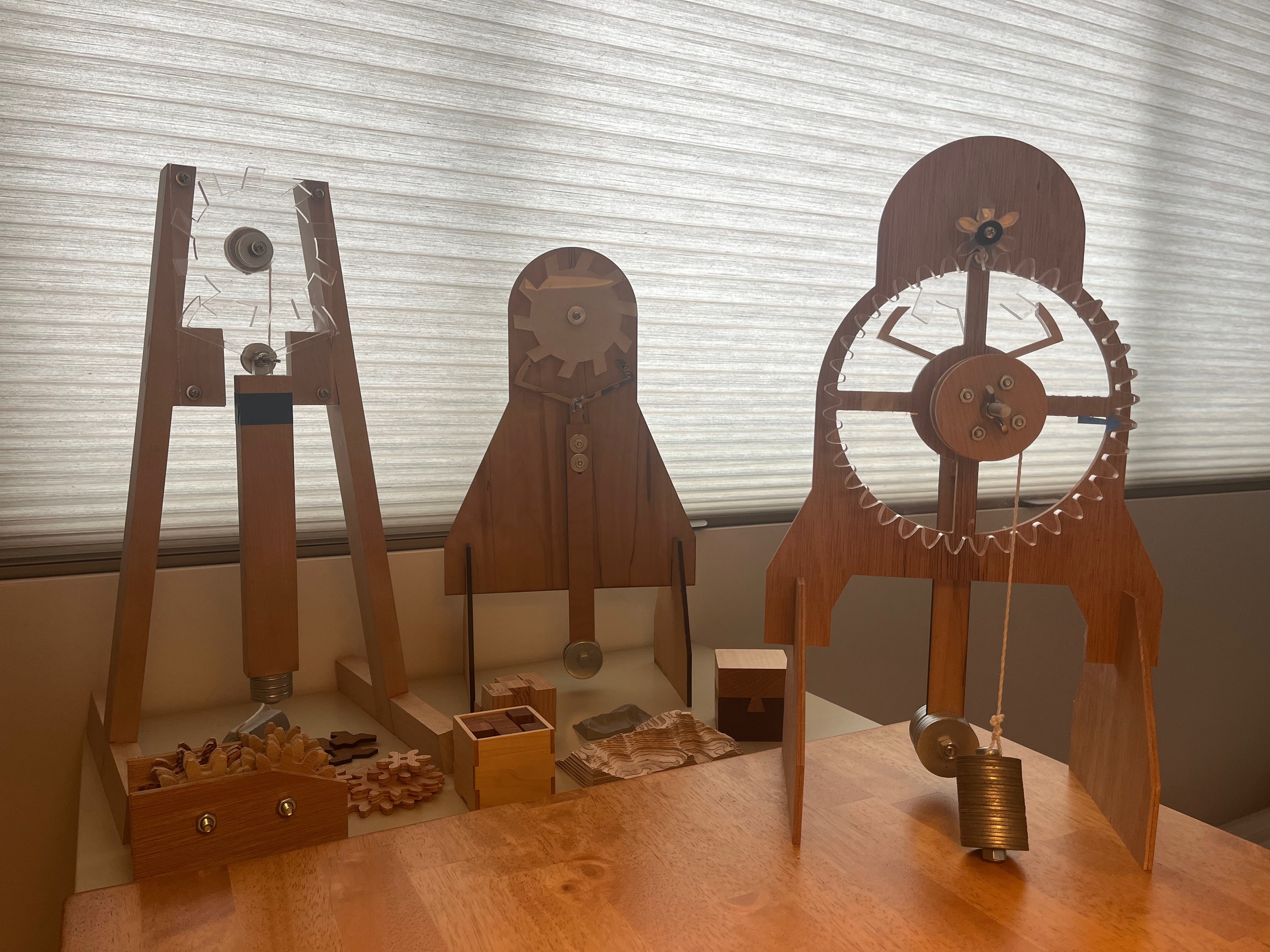
Three generations of my desktop clockwork toy, developed over a period thirteen years (2012-2025). What started as a physics simulation in javascript is slowly turning into a desktop clock.
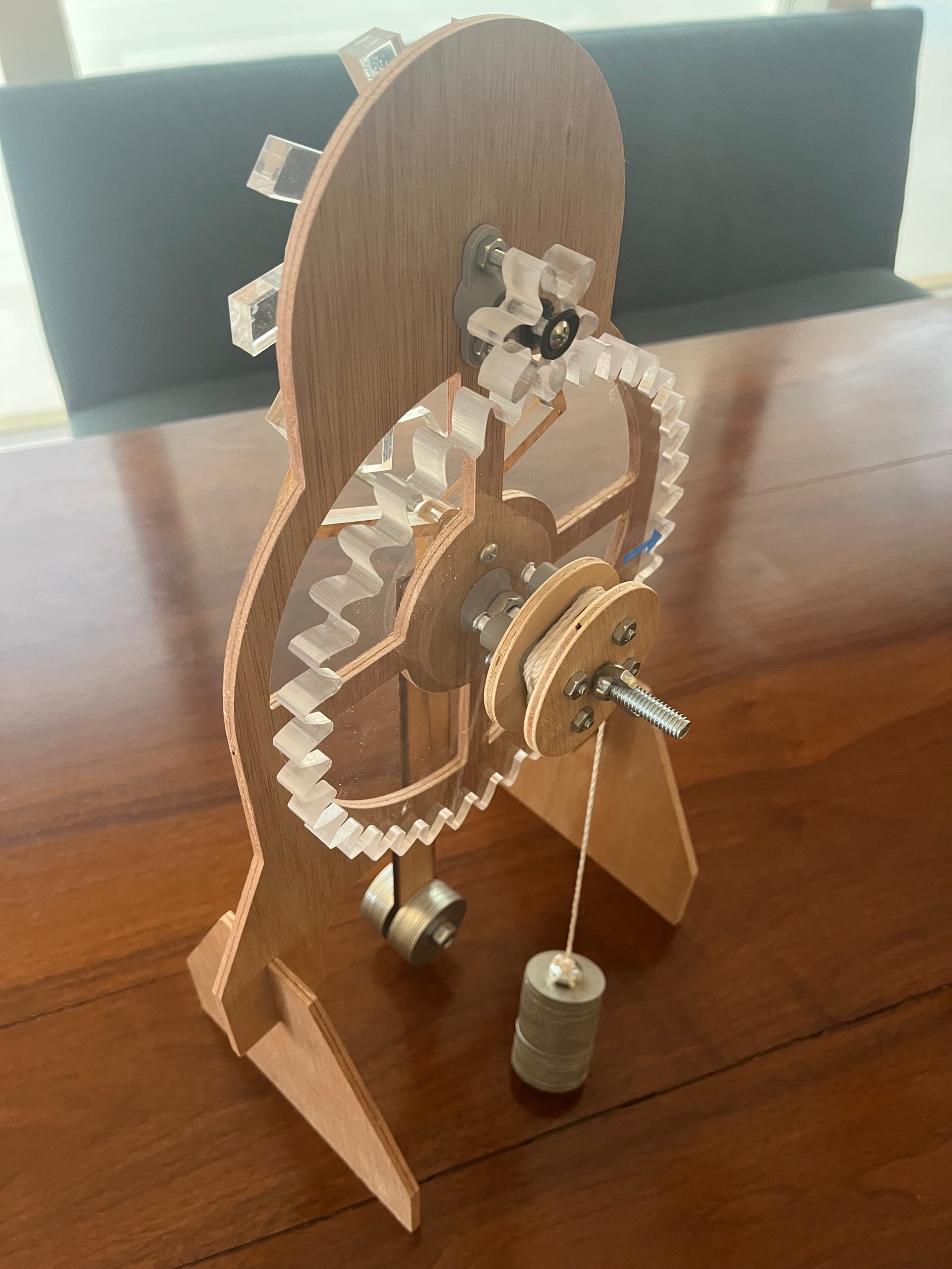
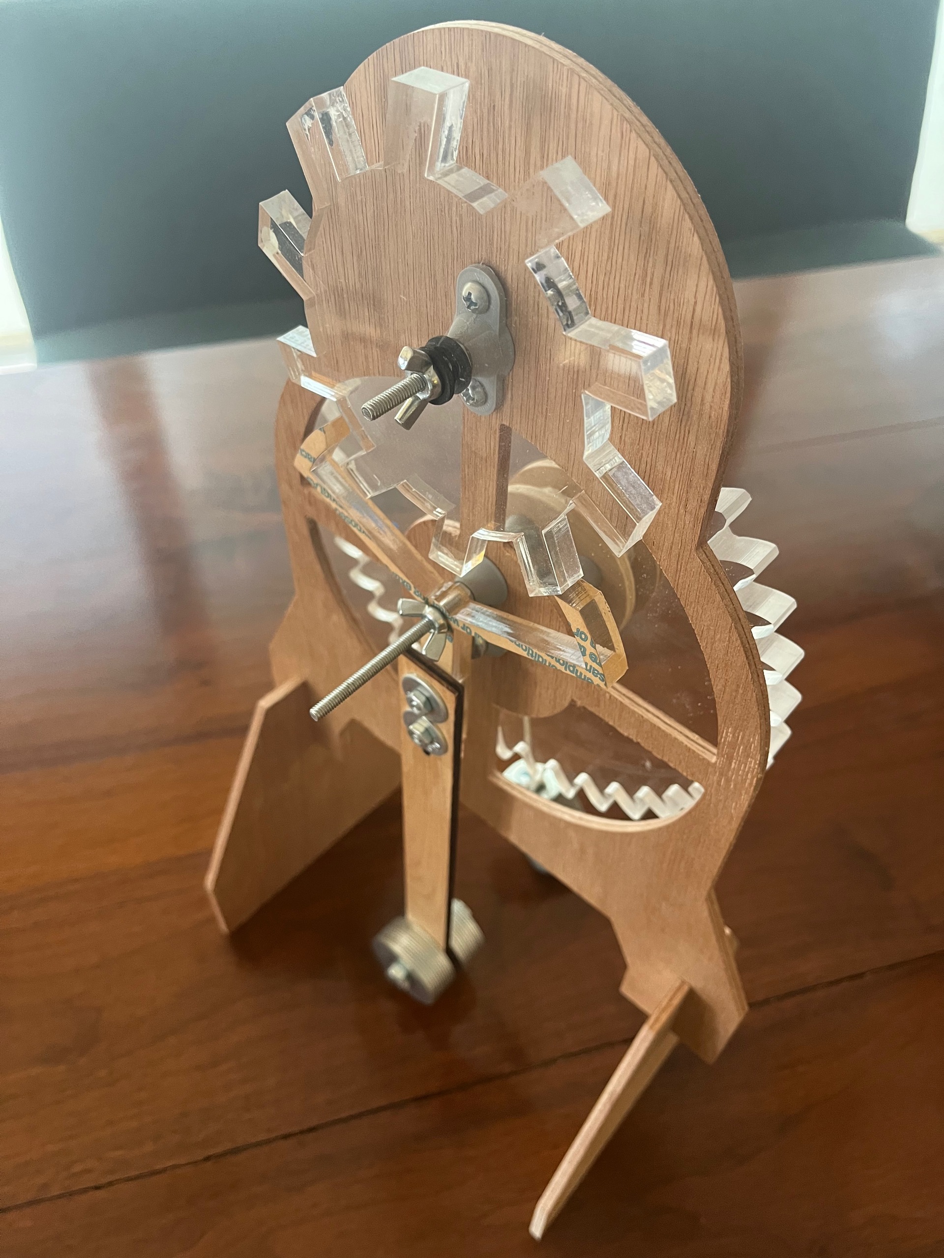
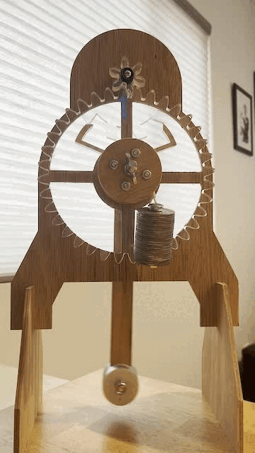
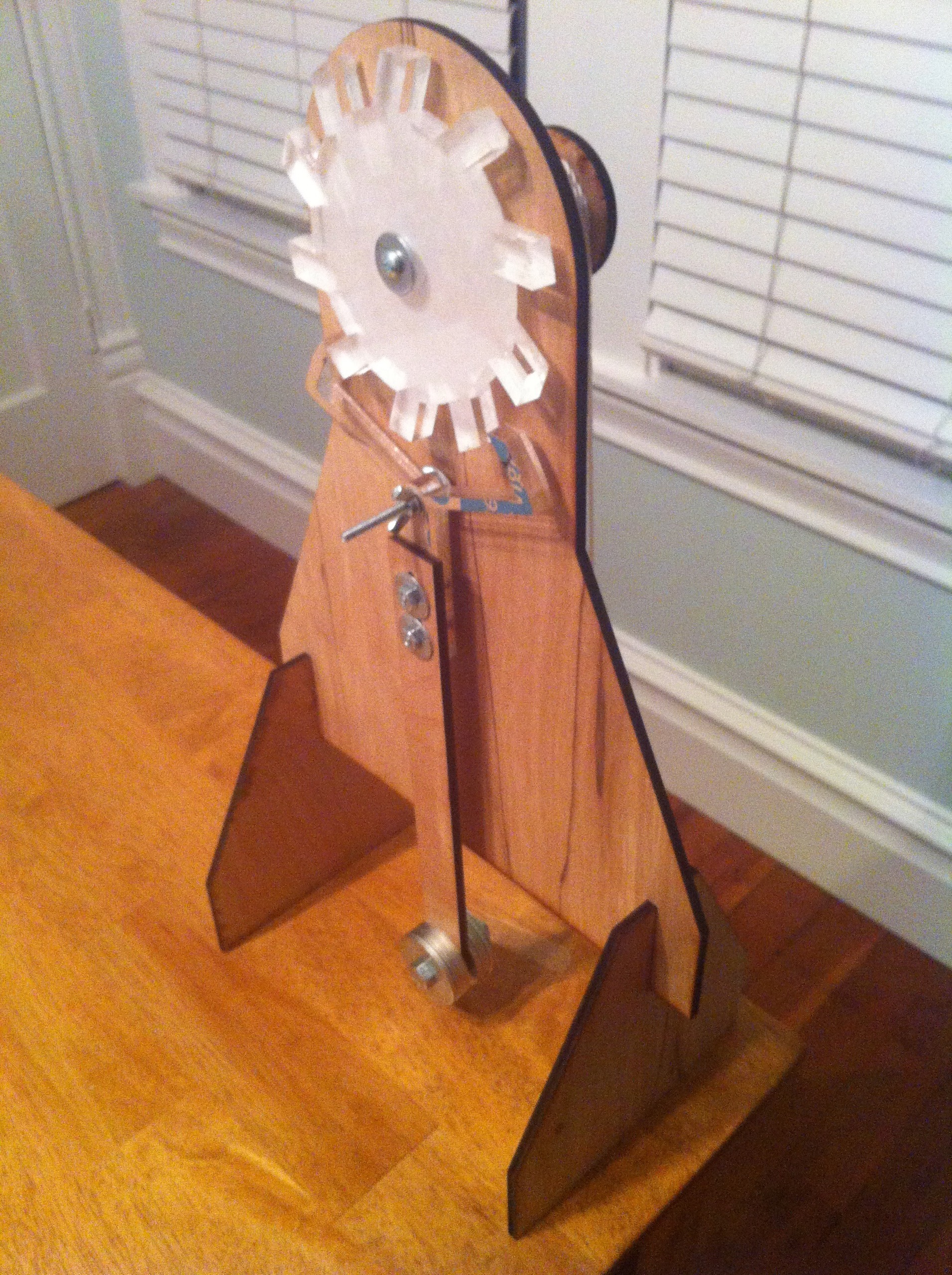
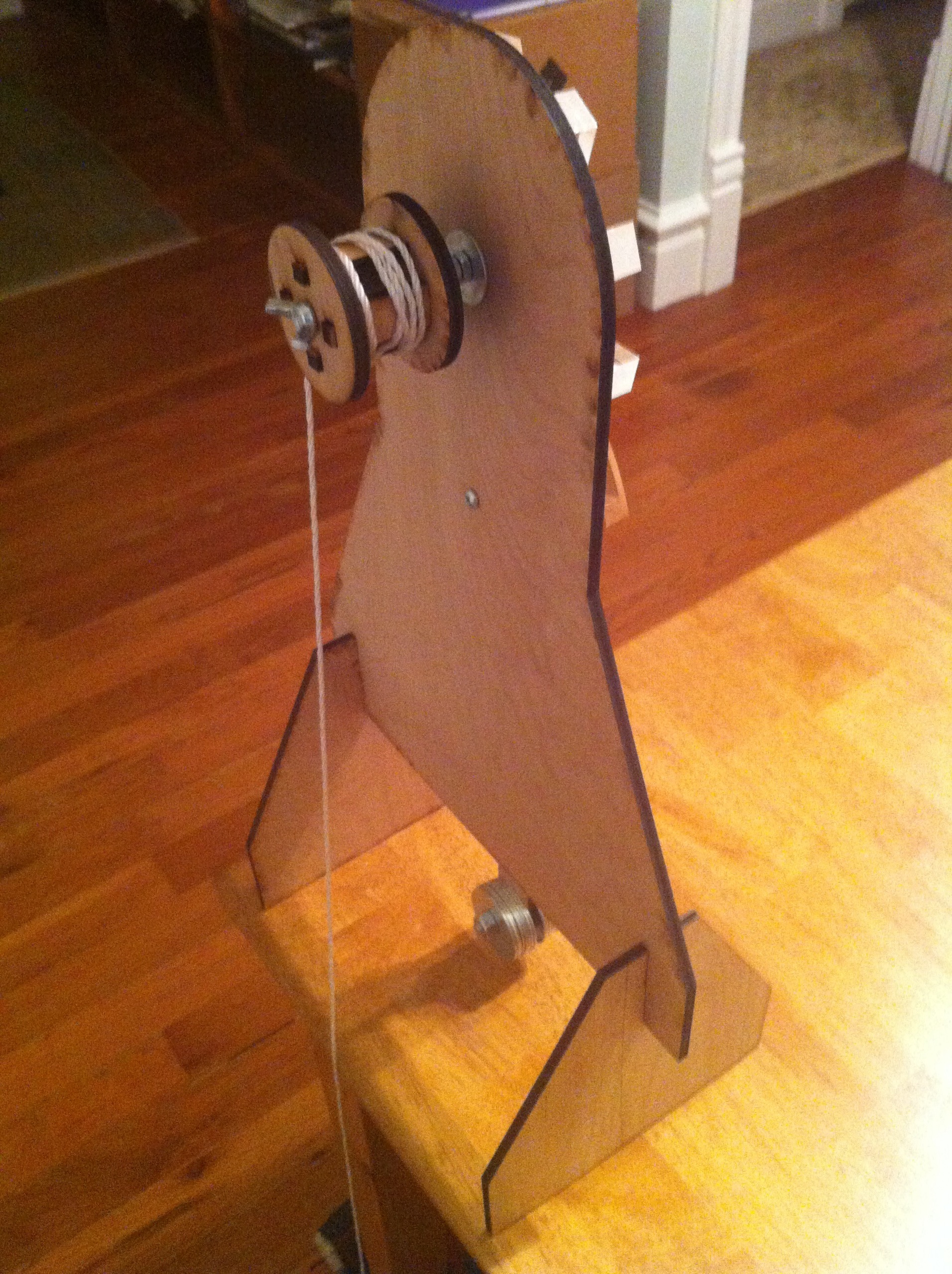
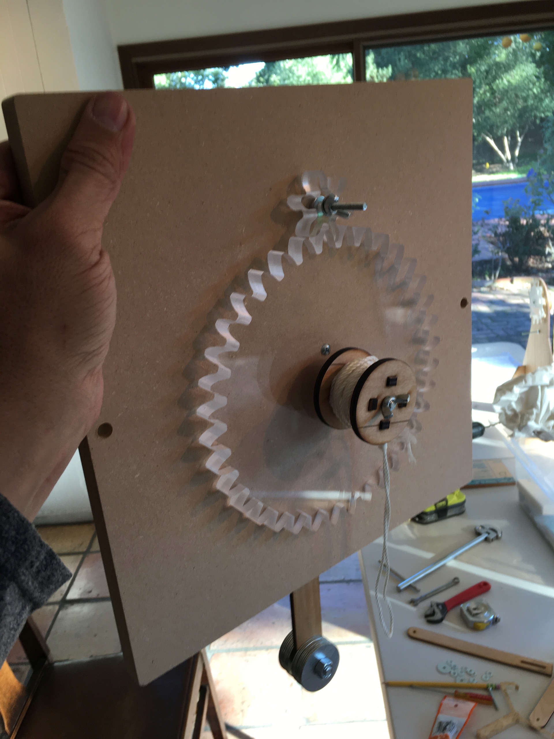
The latest version runs for a little over a minute before the weight lands on the desk, dropping 4.7 inches per minute as it unwinds from the 1.5 inch diameter spool attached to the 36 tooth seconds gear.
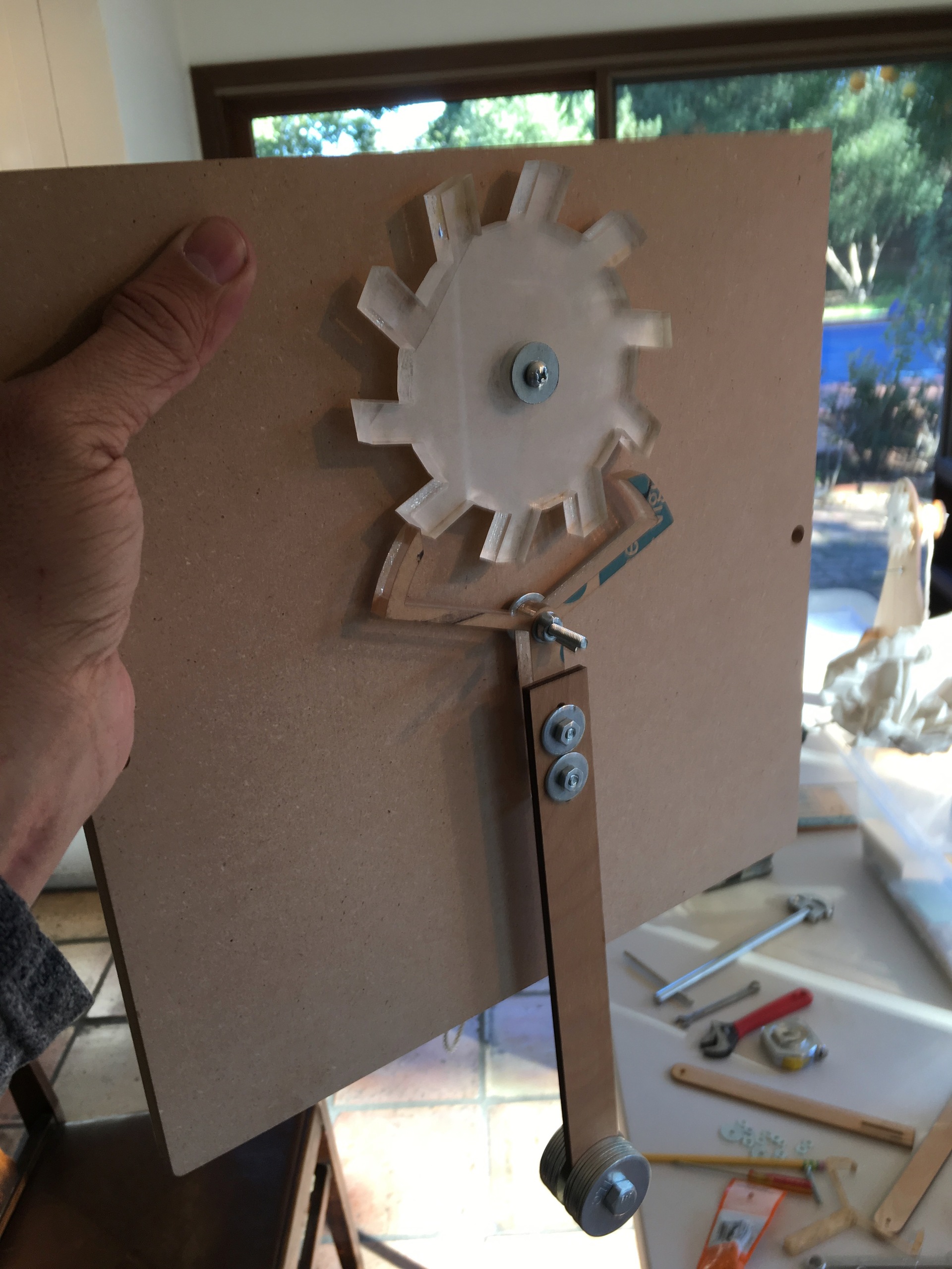
The 36 tooth gear drives a 6 tooth gear attached to a 10 tooth escape wheel that is regulated by a deadbeat anchor attached to a pendulum with a period of 1 second.
I measured the accuracy by writing some python code to analyze the audio track of the video recording and detect the ticks as the anchor pallets strike the escape wheel. After some fine adjustment to the length of the pendulum, I have it oscillating at 1.00133 Hz, gaining just 1.33 ms per second or 80 ms per minute. I'm pretty happy with that!
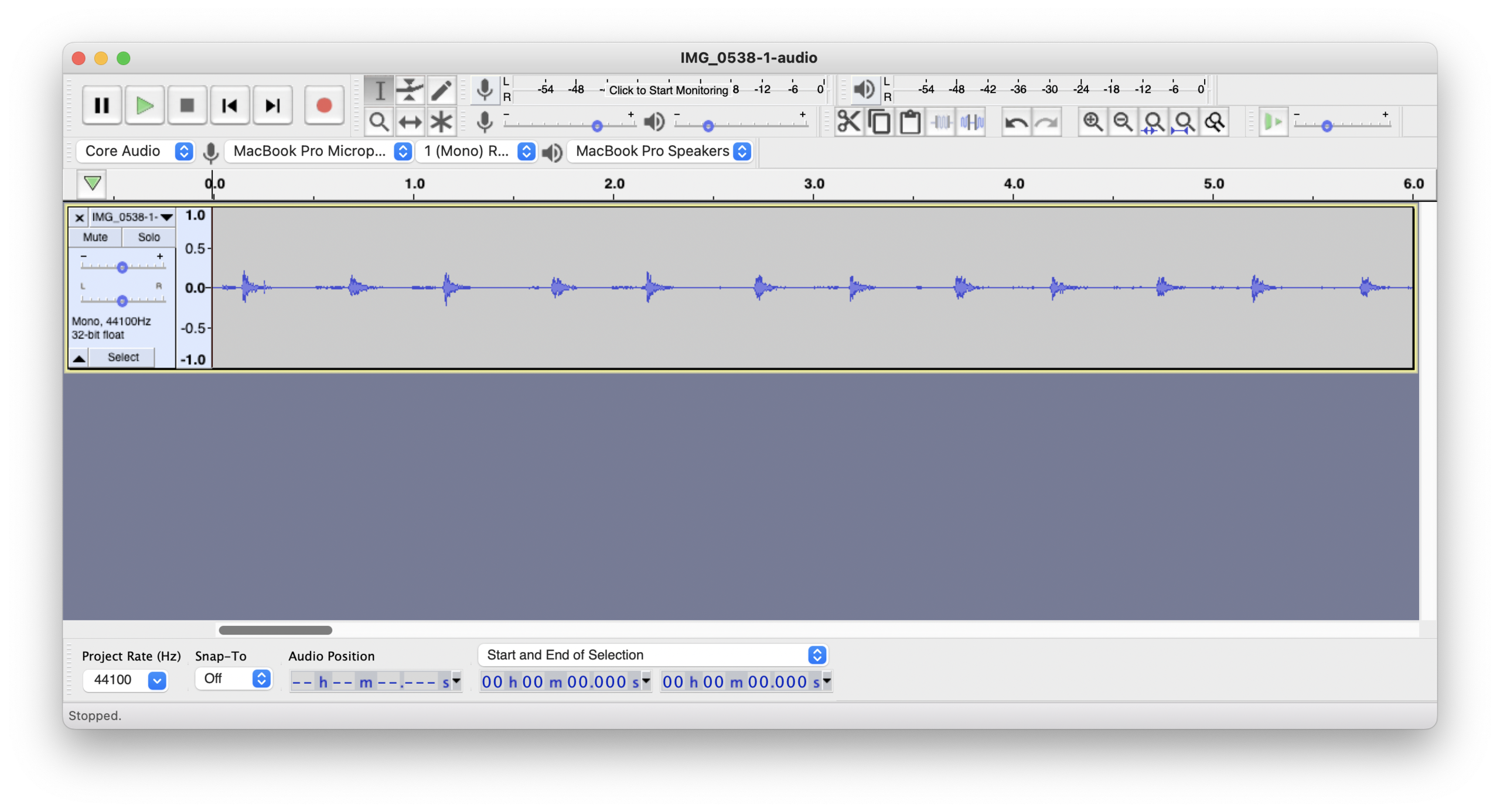
% python3 detect.py IMG_0538-1.mov

avg 500.6666666666667 ms per tick

period 1.0013333333333334 seconds

error
1.3333333333333712 ms per second
80.0 ms per minute
Extracting frames from the video at 1 second intervals you can see that the pendulum appears to be mostly stationary, with just a little jitter.
History
2012
Winding back the clock to 2012, I was playing around with a javascript port of the Chipmunk physics engine (I had just used Chipmunk to implement physics in the iOS game Hakenbush) and I got the idea to try simulating an escapement mechanism.
I found the website http://www.abbeyclock.com/escapement.html and using the online book Clock and Watch Escapement Mechanics as a design guide got a deadbeat escapement running in a web browser
Of course I couldn't stop with a simulation and immediately started thinking about how to build one in real life.
I found a 3d model of the same deadbeat escapement design on thingiverse https://www.thingiverse.com/thing:7785 and updated my simulation to use that
I then used the 3d model to generate files for laser cutting and had them cut out of acrylic at an art collective that I had access to (my first experience with laser cutting)
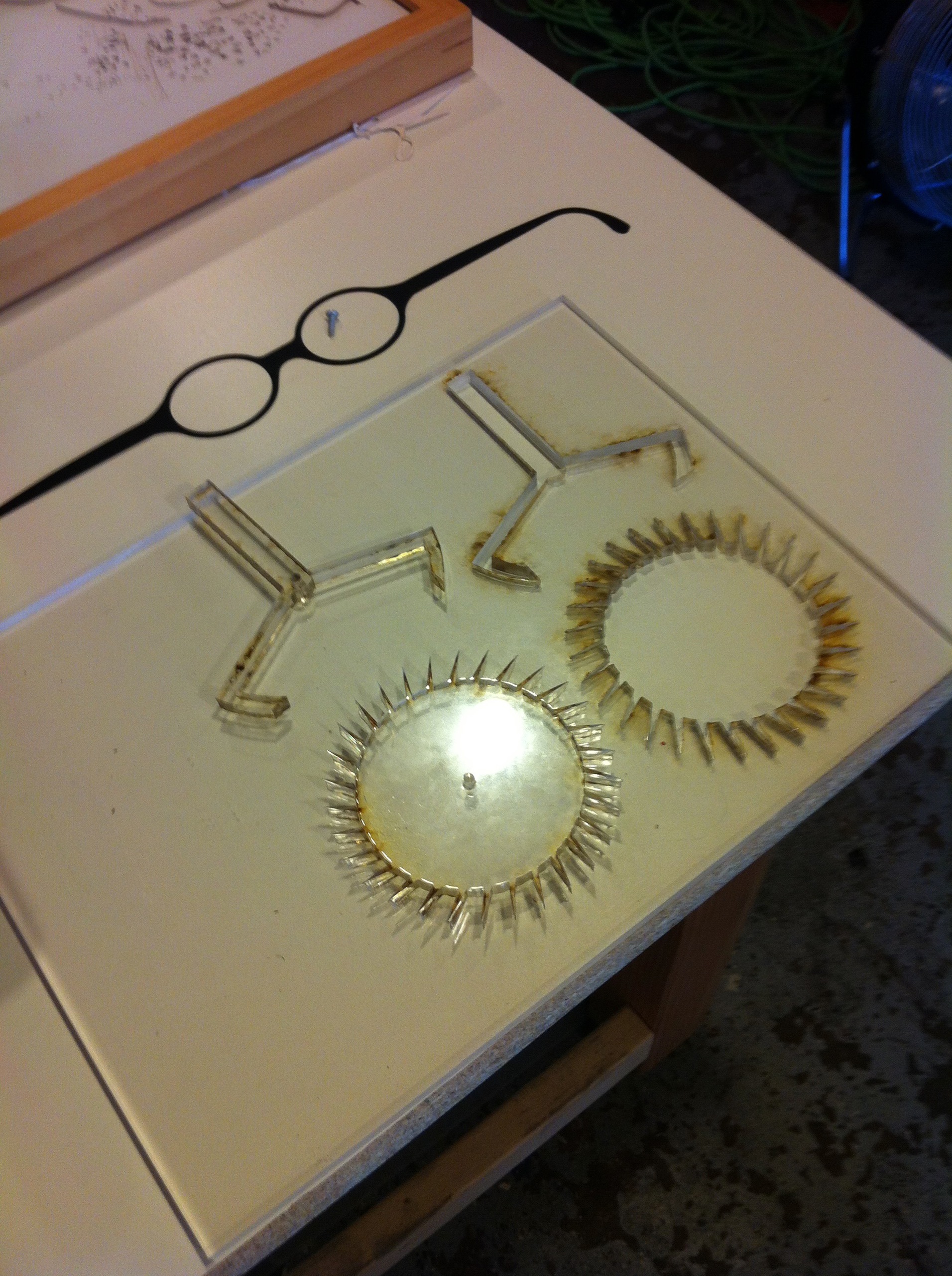
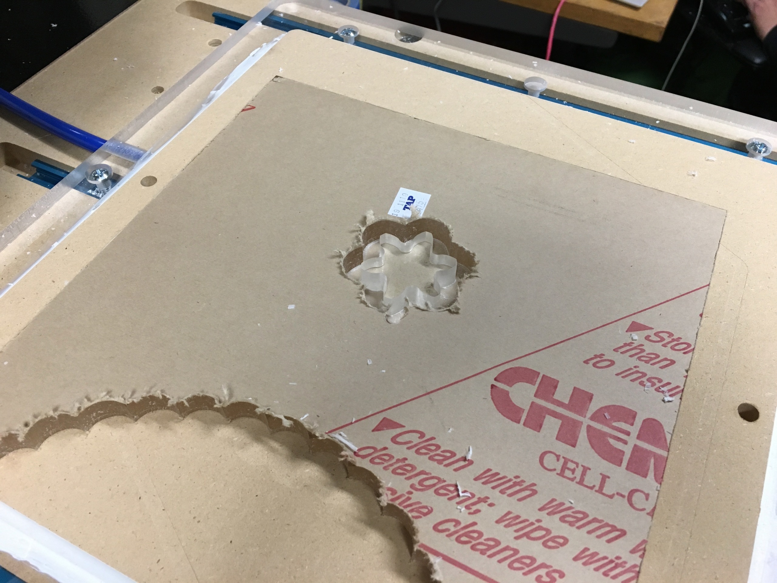
Those first parts were too fragile, so I reduced the number of teeth in the escape wheel and tried again.
Success! My first prototype used a 0.9936 meter long pendulum with a one second tick (two second period)
My later prototypes, designed to sit on a desktop, used a shorter 0.2484 meter long pendulum with a half-second tick (one second period).
The first desktop prototype was handbuilt in my woodshop
I next designed a stand, spool, and pendulum for laser cutting and had those cut out of plywood at the art collective
2017
Life got busy, we moved, and I put the project aside until 2017, when I started designing a gear train to drive a seconds hand.
With the escape wheel making one revolution every 10 seconds, I decided on a 36:6 gear reduction to get one revolution per minute.
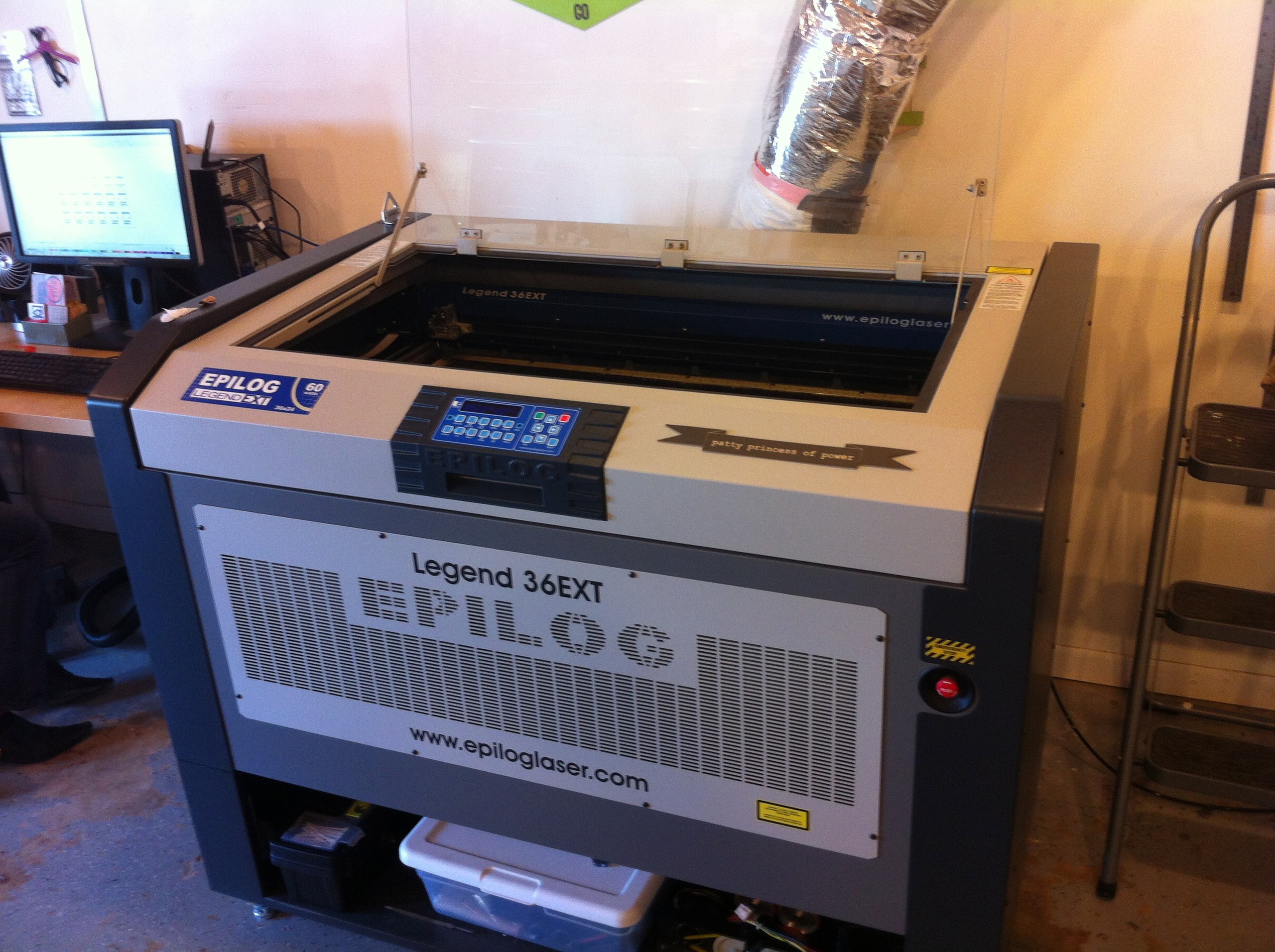
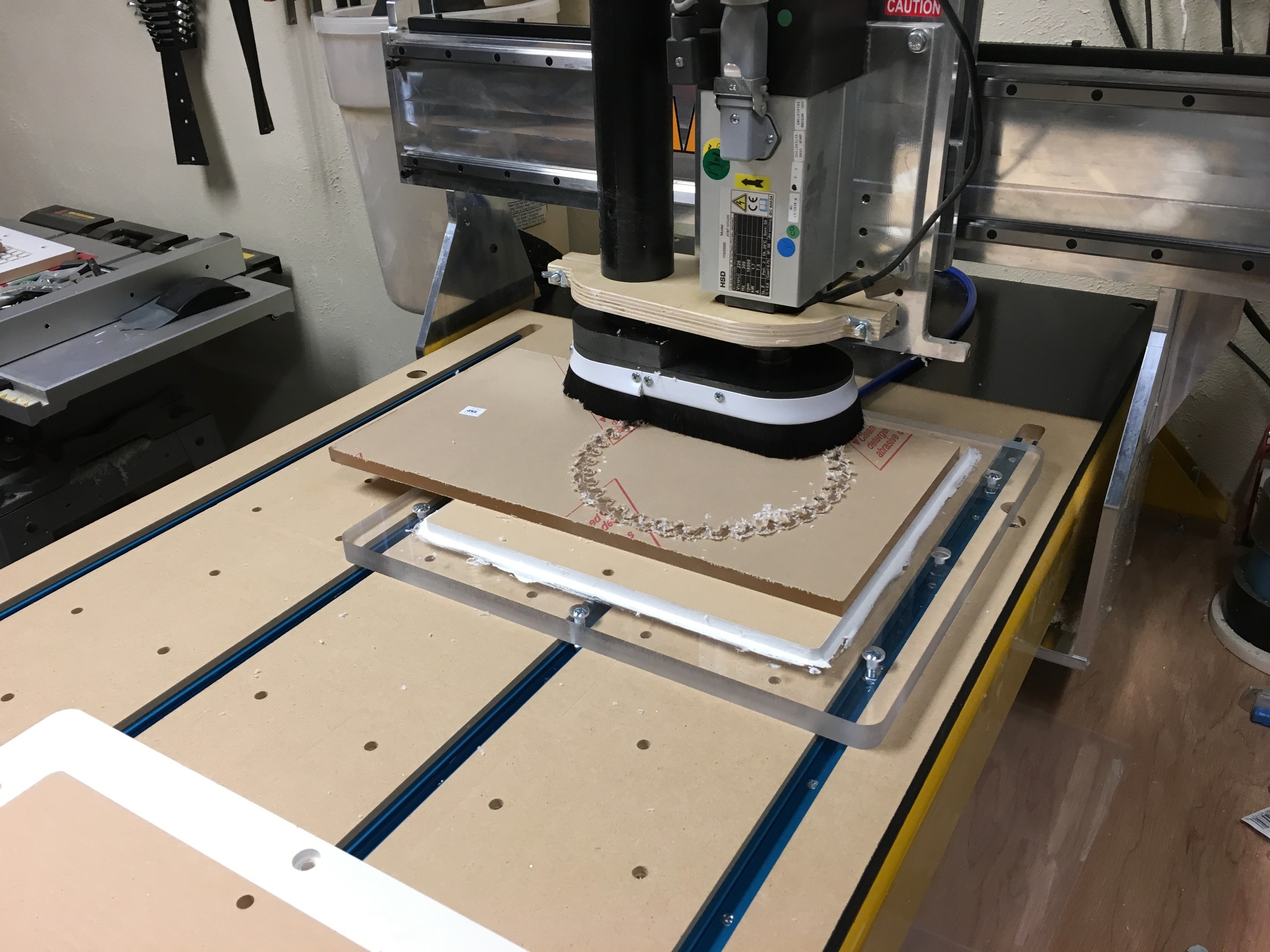
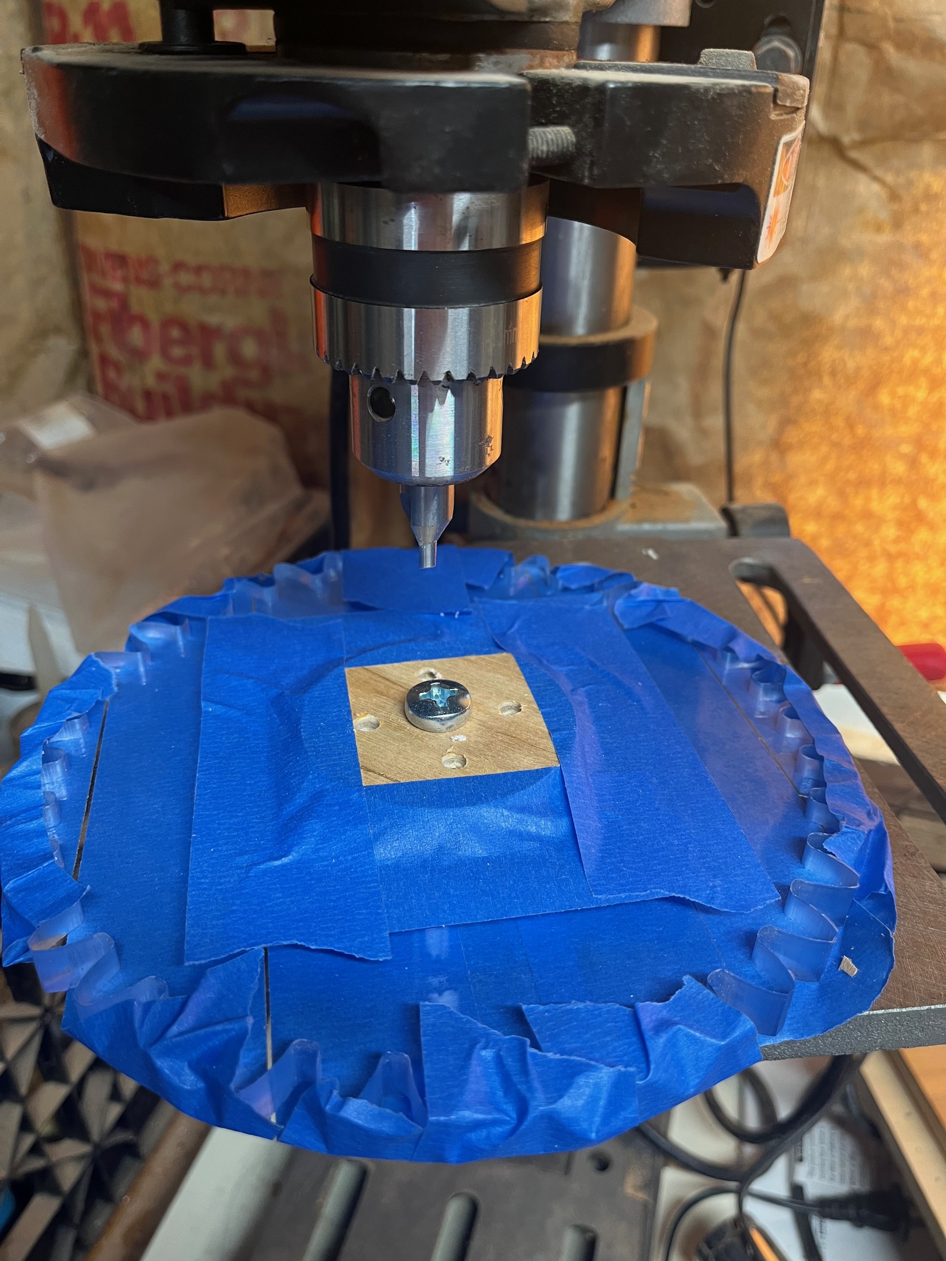
I no longer had access to a laser cutter, but I now had a friend with a cnc machine who helped me cut the gears out of acrylic (my first experience with cnc machining)
2022
Life got busy again and it wasn't until 2022 that I started working on a new stand to hold the gear train.
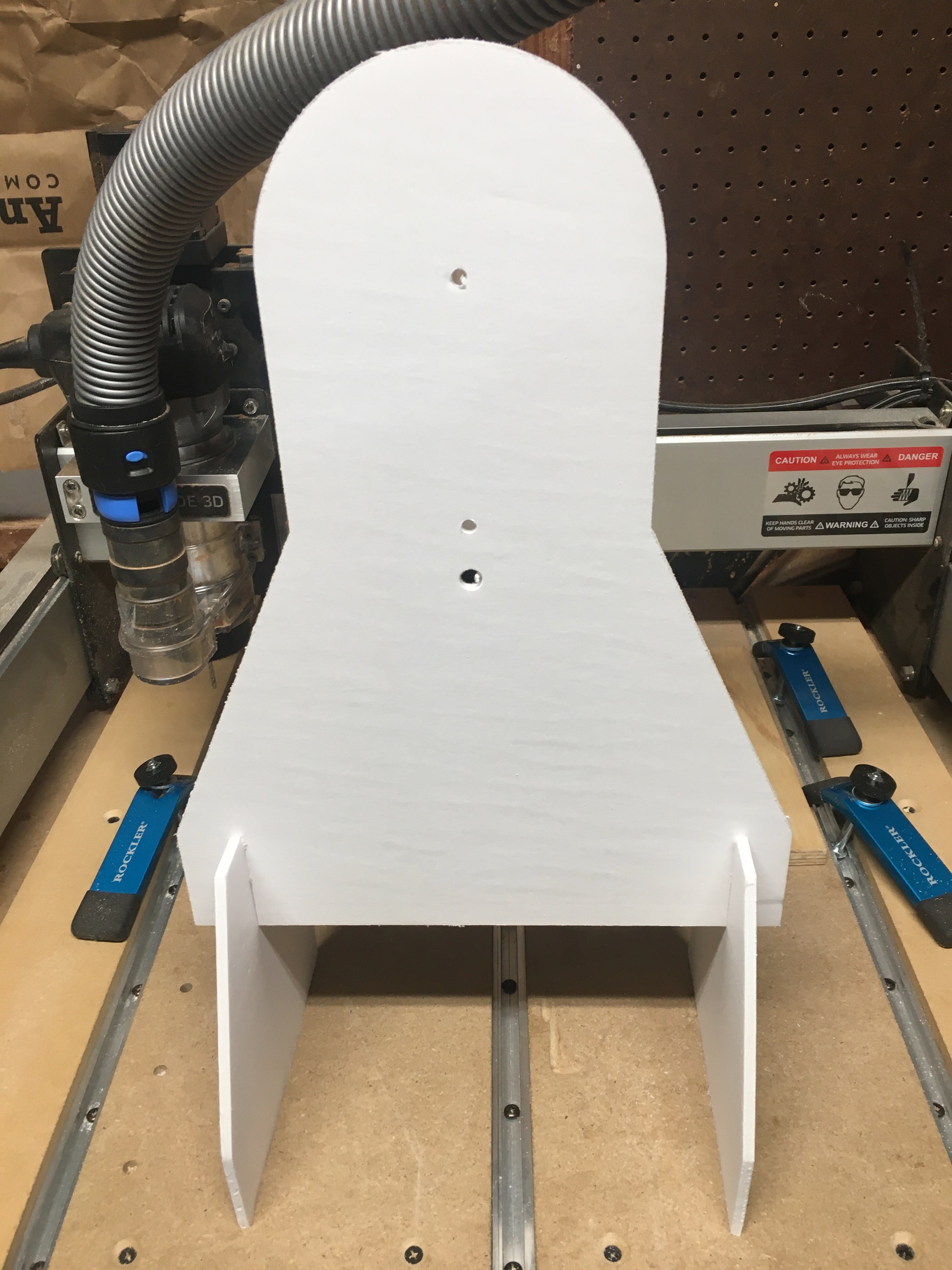
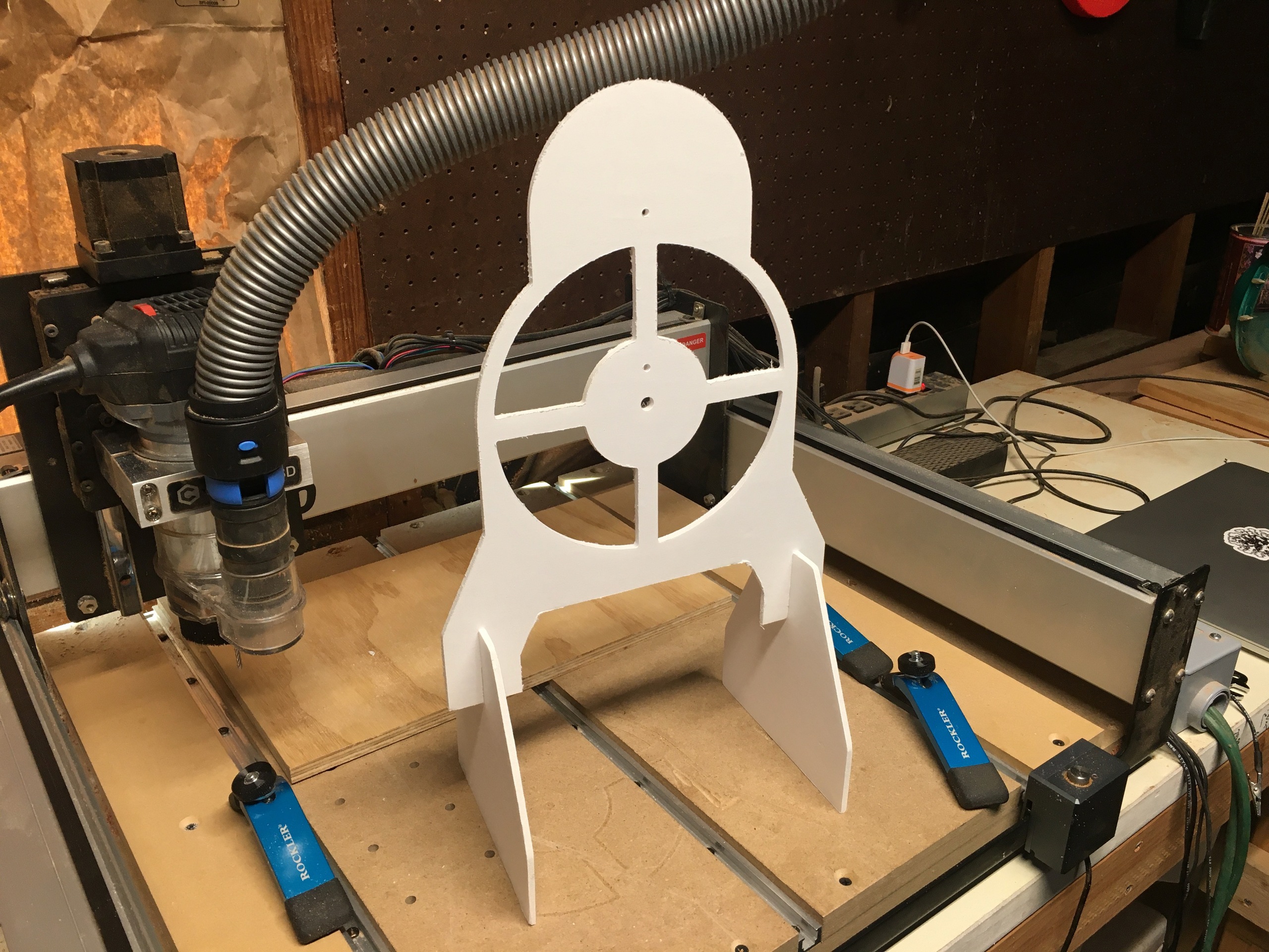
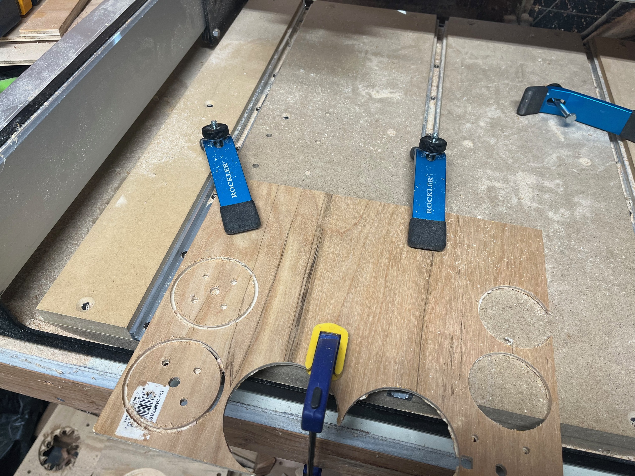
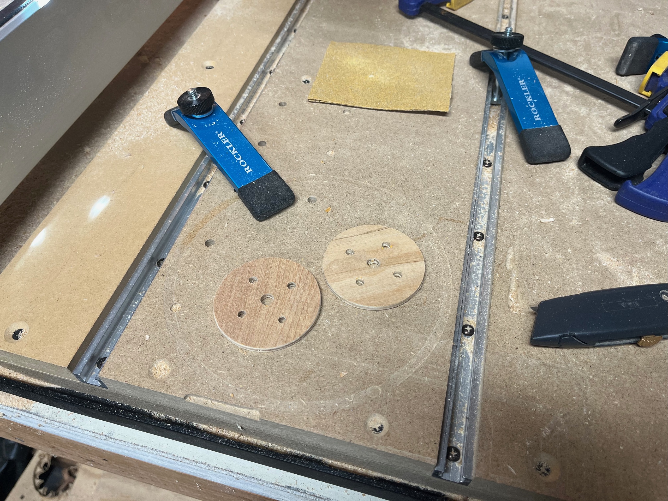
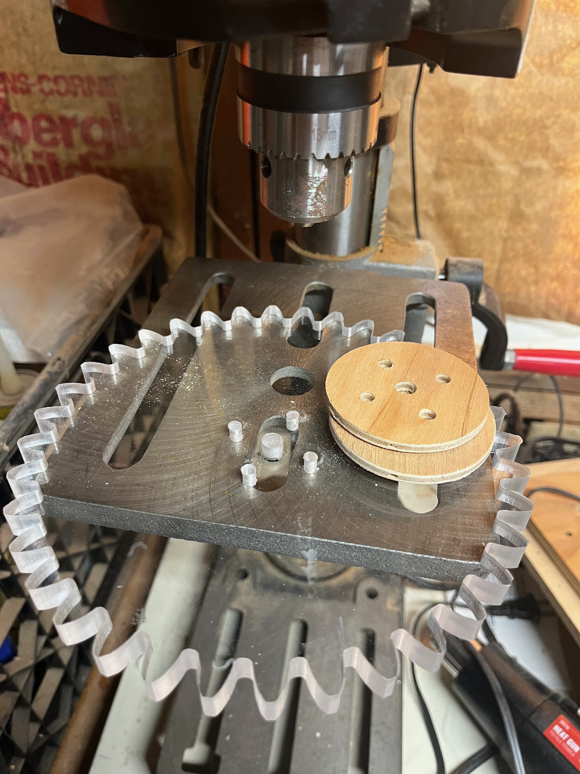
By now I had my own cnc router, so I started by redesigning the laser cut stand for cnc cutting, prototyping it in foam core
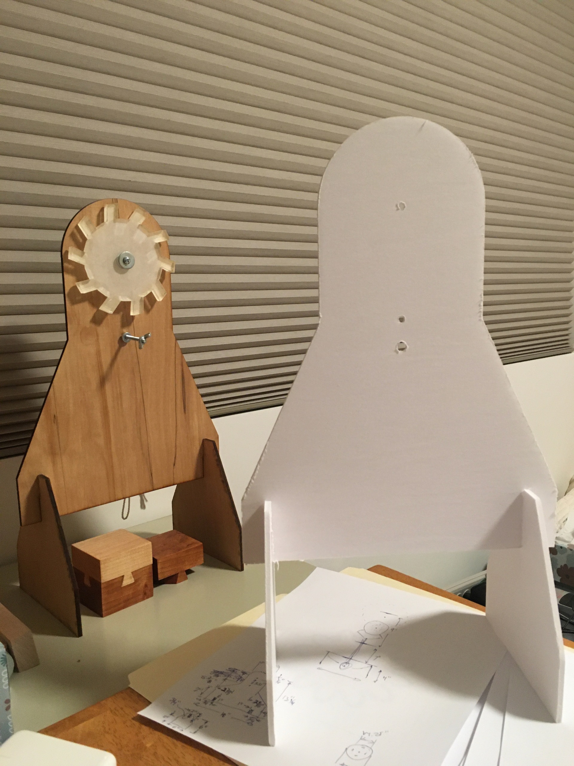
With that working I modified the design to accomdate the gear train and cut it out of plywood
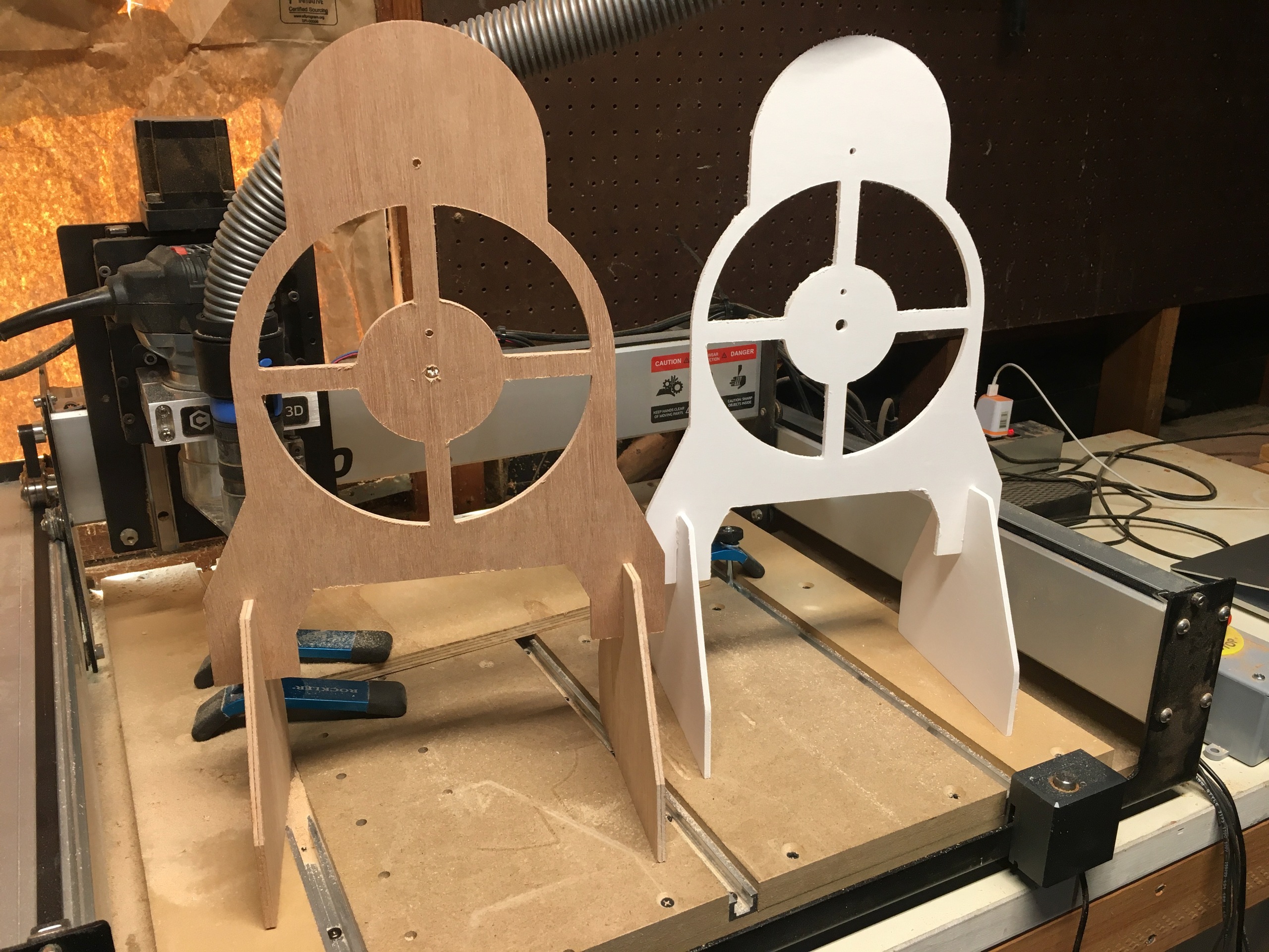
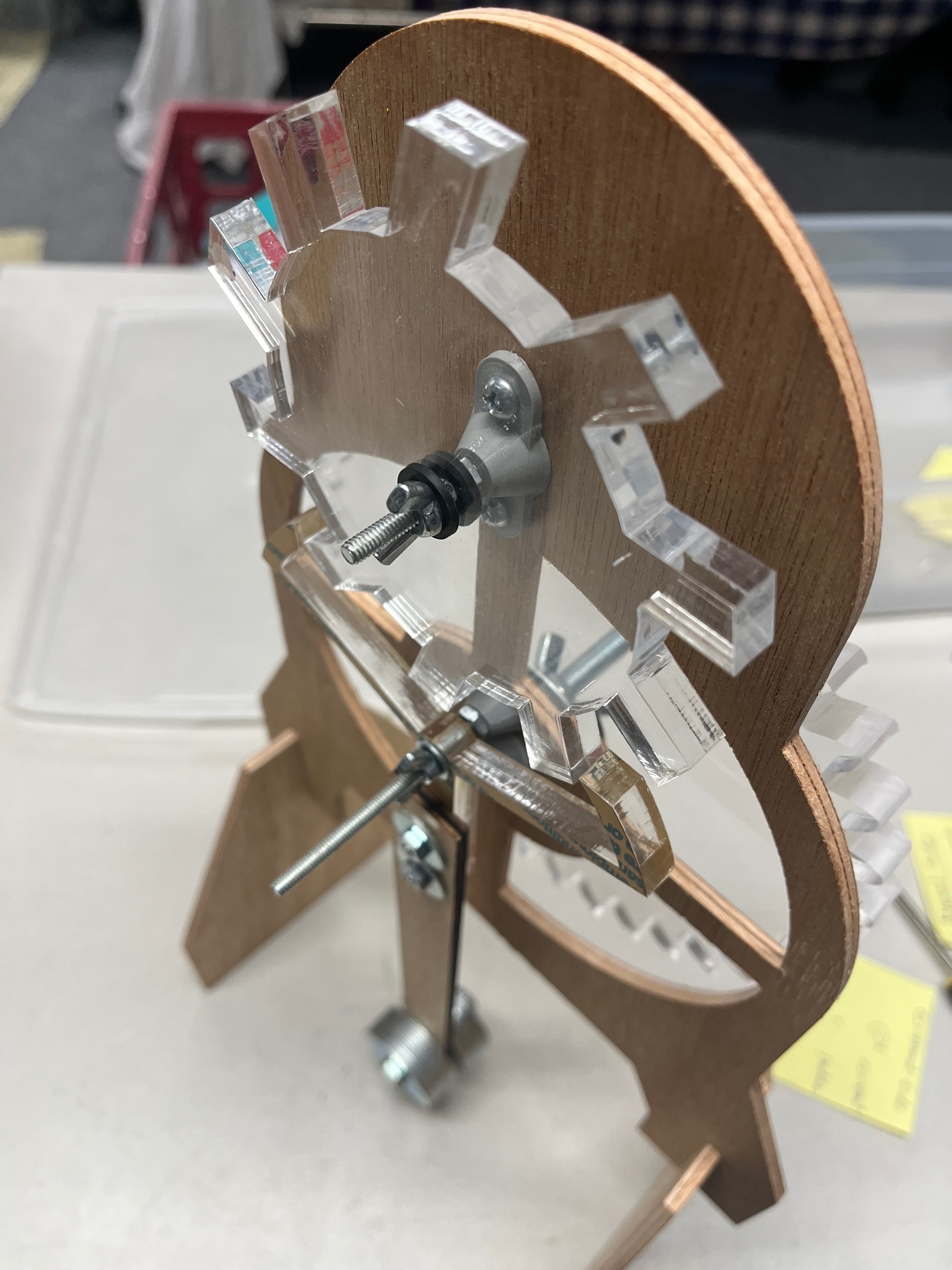
The layout was good, but there was room for improvement in the way that the shafts were mounted, just bolts through holes in the 1/8" plywood, allowing too much play and leading to binding and energy loss.
2025
Finally, in 2025, inspired by watching Clickspring and Wristwatch Revival on YouTube, and a coversation with a friend who repairs clocks and watches, I started thinking about how to improve the mounting of the gears.
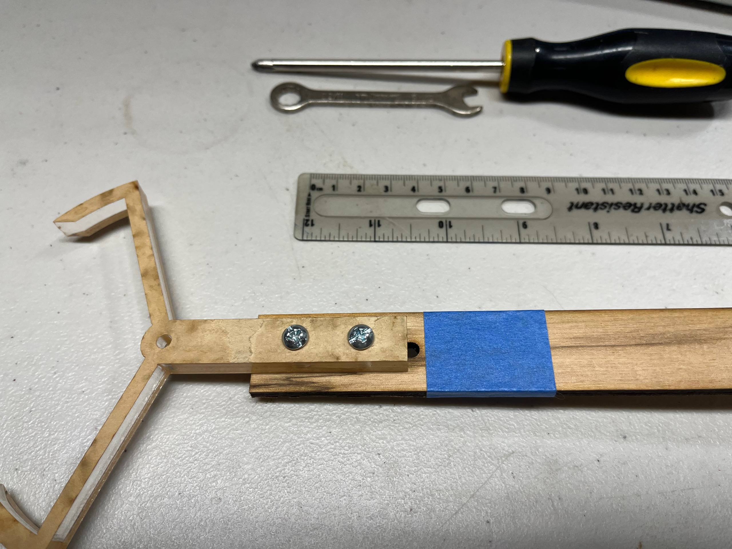
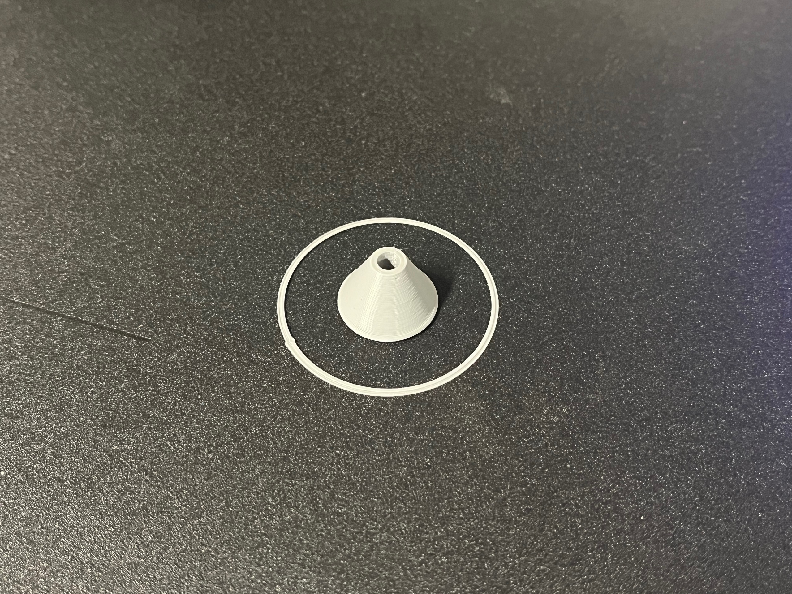
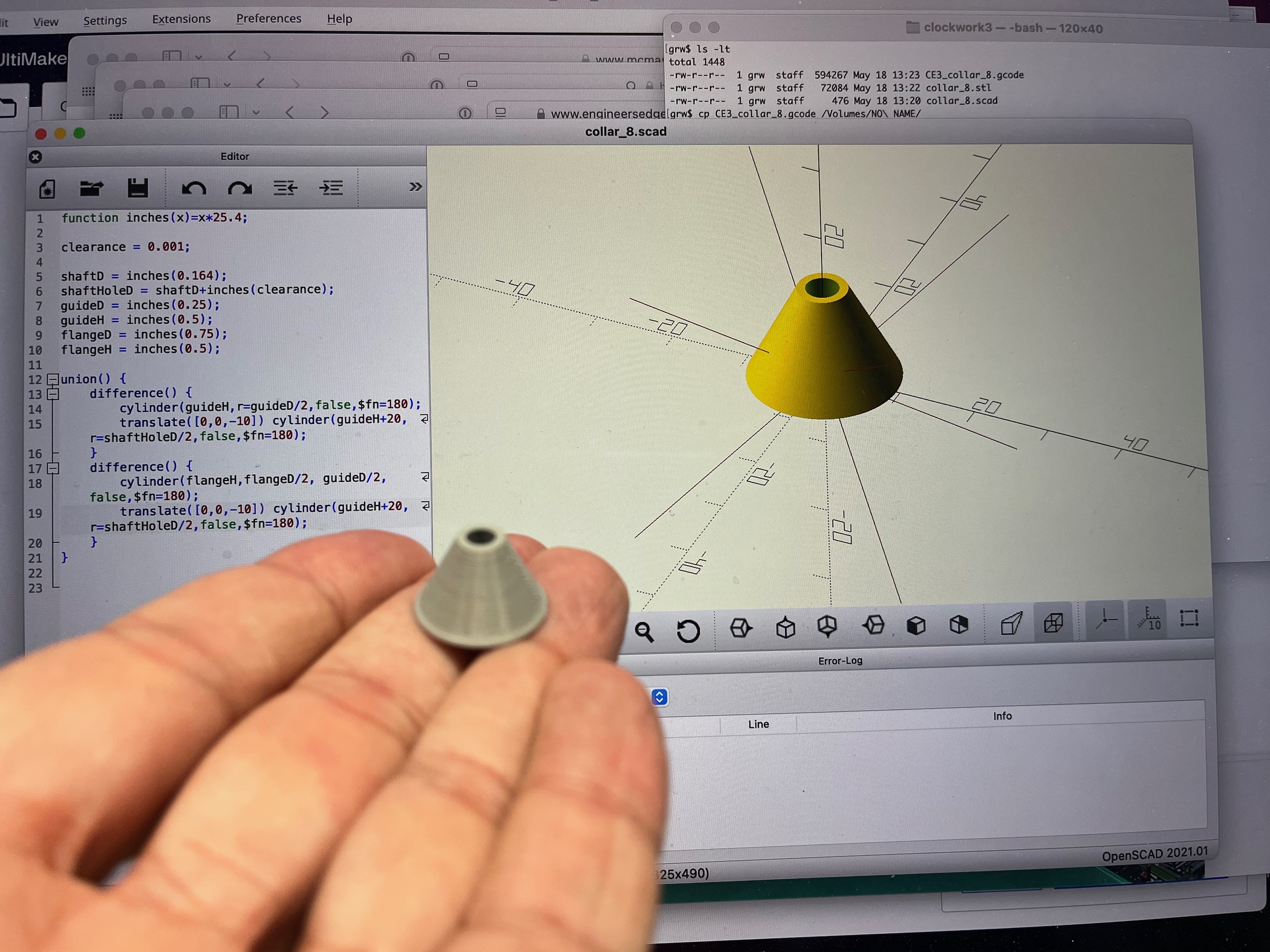
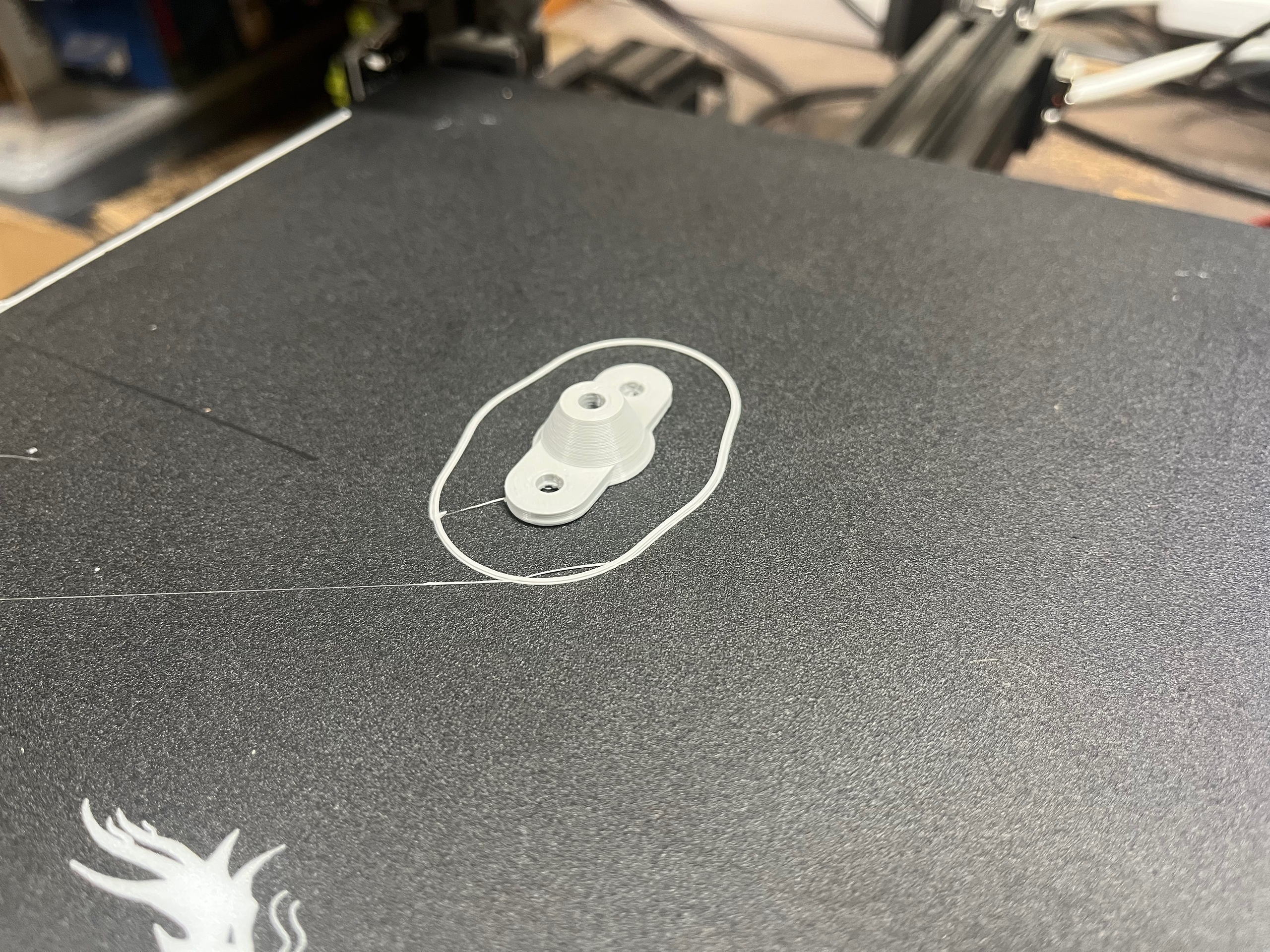
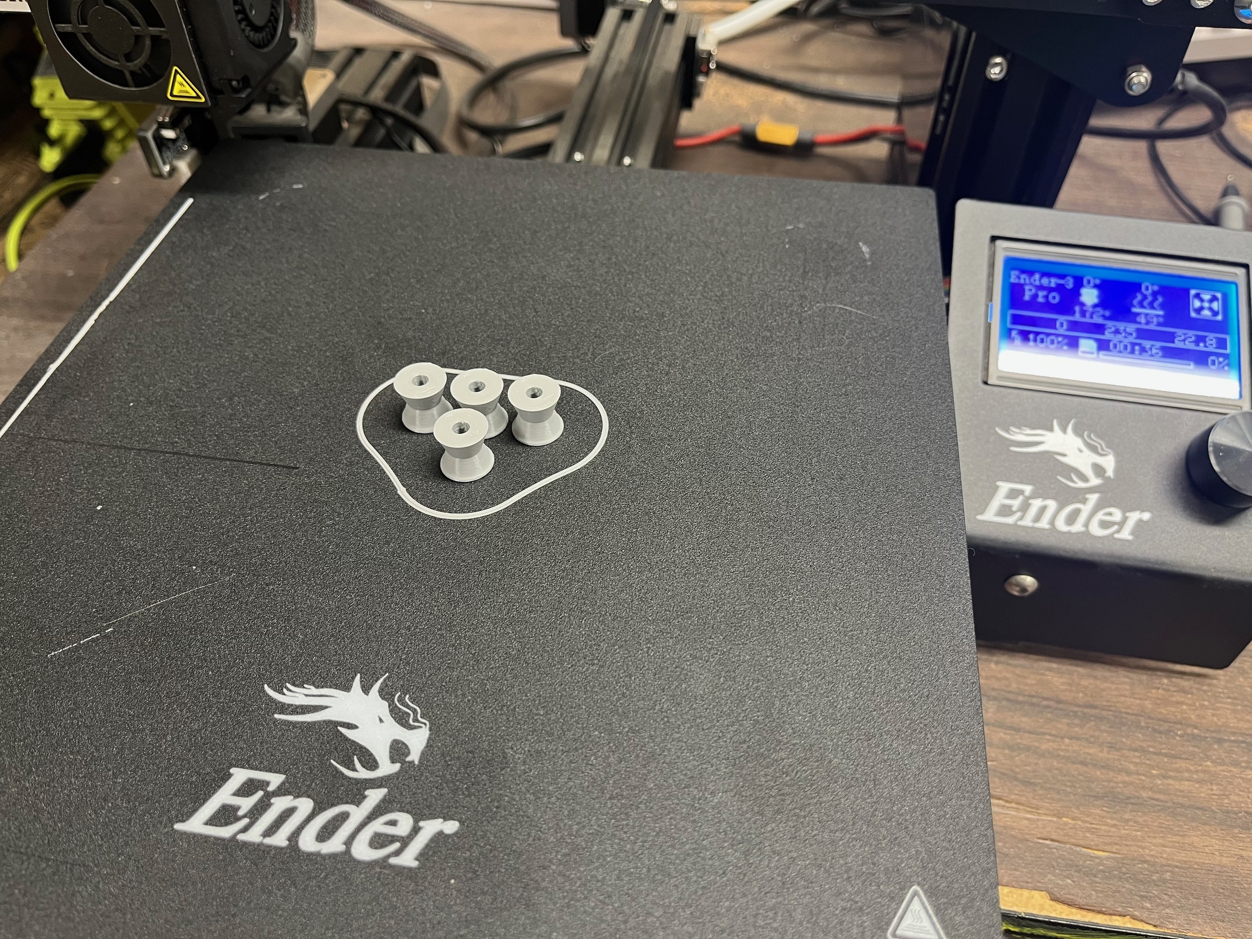
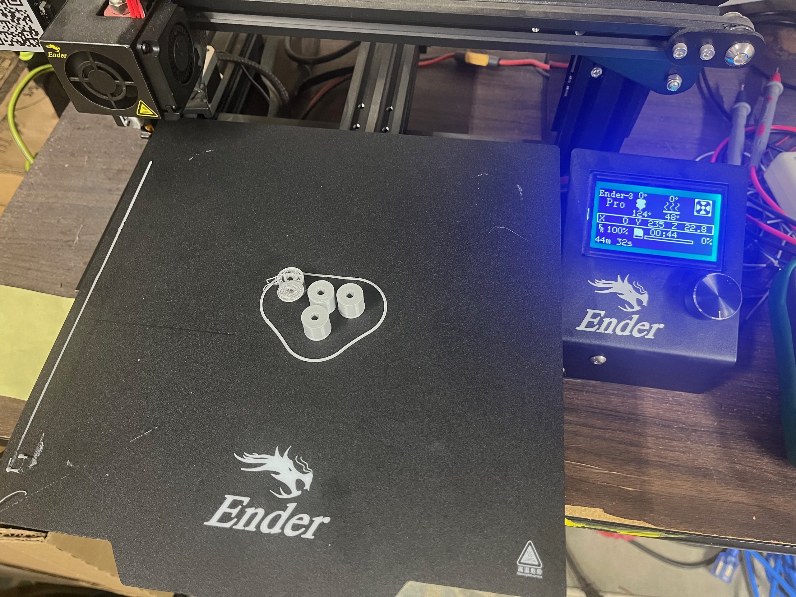
I could have added more frame pieces, capturing the shafts on both sides of the gears, but I wanted to keep the mechanism fully visible. I could have made the frame thicker, providing more support for the shafts in between the gears, but I wanted to reuse the parts I had if at all possible. In the end I decided to 3d print some parts to extend the width of the frame only where the support is needed
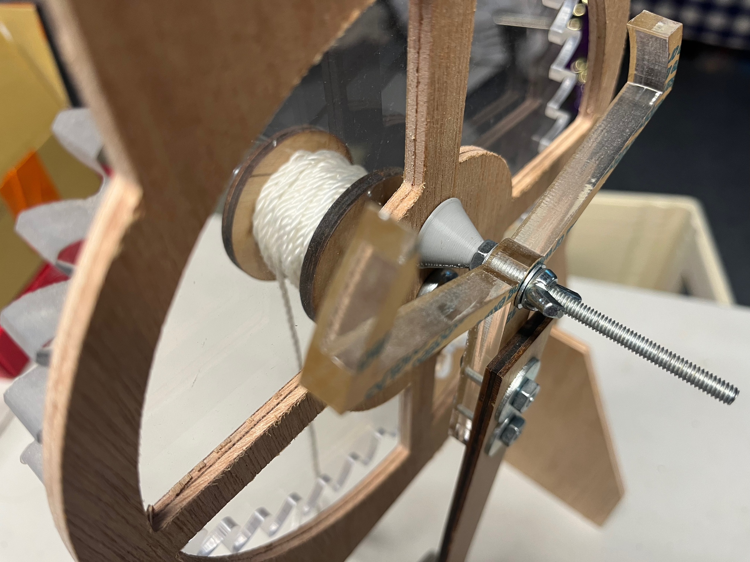
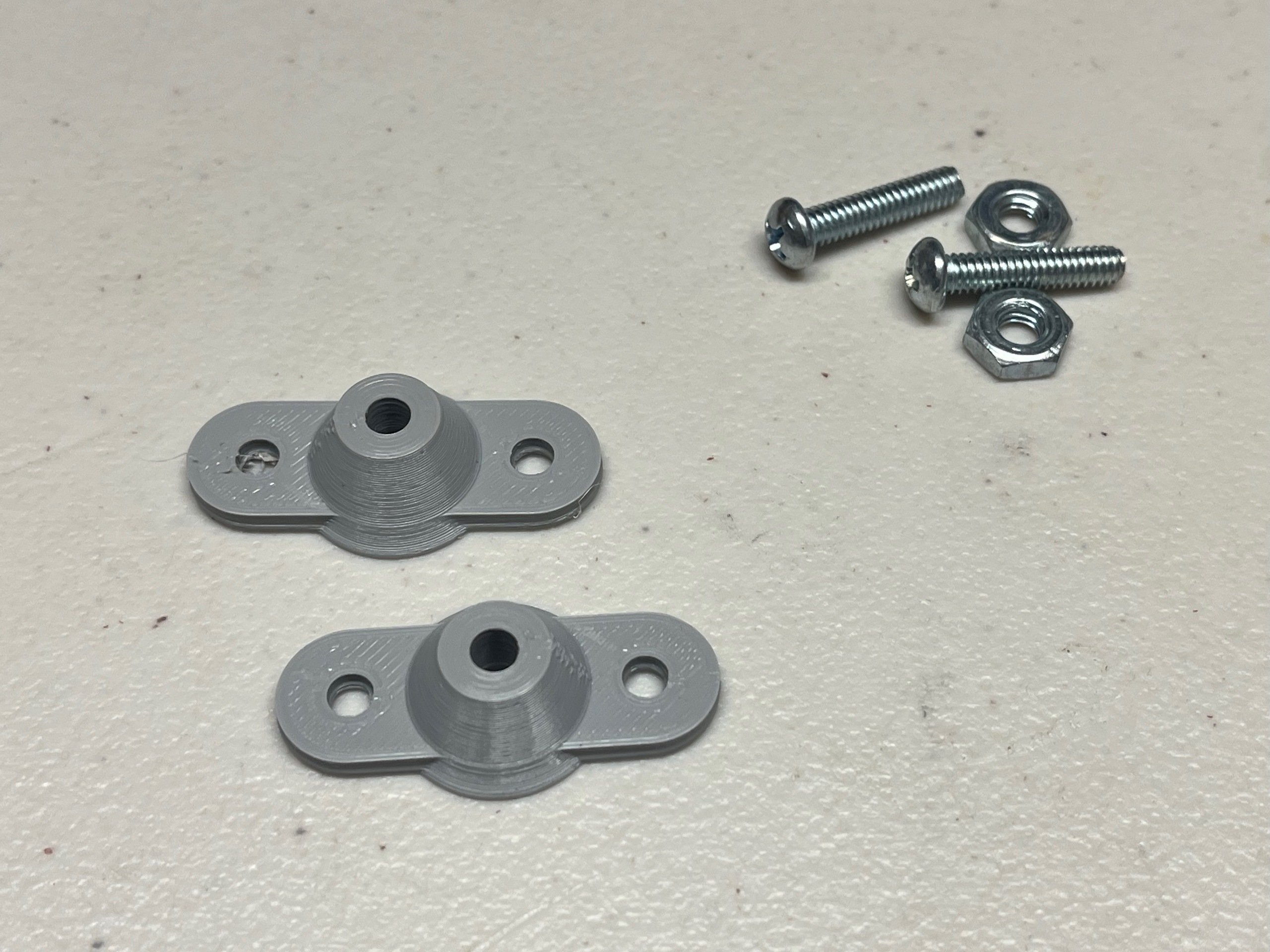
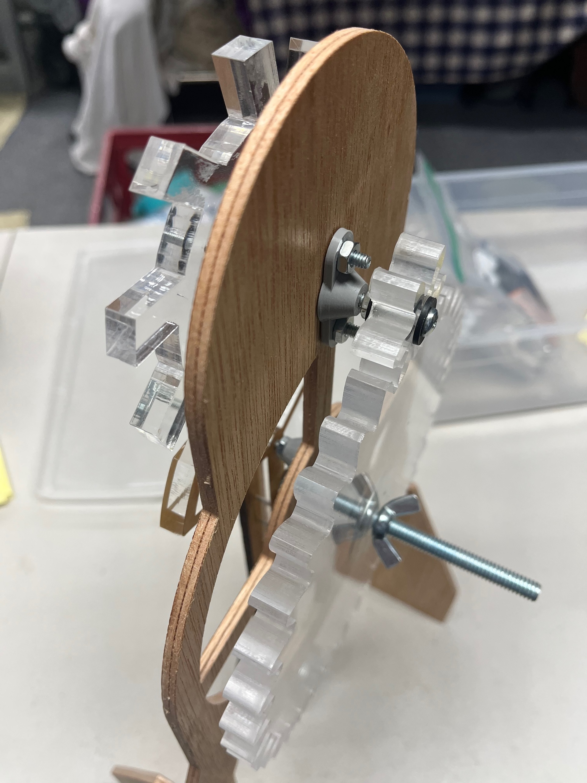
I also redesigned the spool to be attached directly to the large gear, with the two of them rotating together on a fixed shaft instead of being attached to a rotating shaft. This change made a huge improvement to the stability of that shaft, which has to support the weight that drives the clock.
That brings us to the present. I'm pretty happy with this version of the desktop clockwork toy, maybe it's done.
Or maybe I'll be inspired to add minute and hour hands someday, but if I do that I think I might return to a one meter pendulum design and mount it on the wall.