Mt Whitney Model (2022)

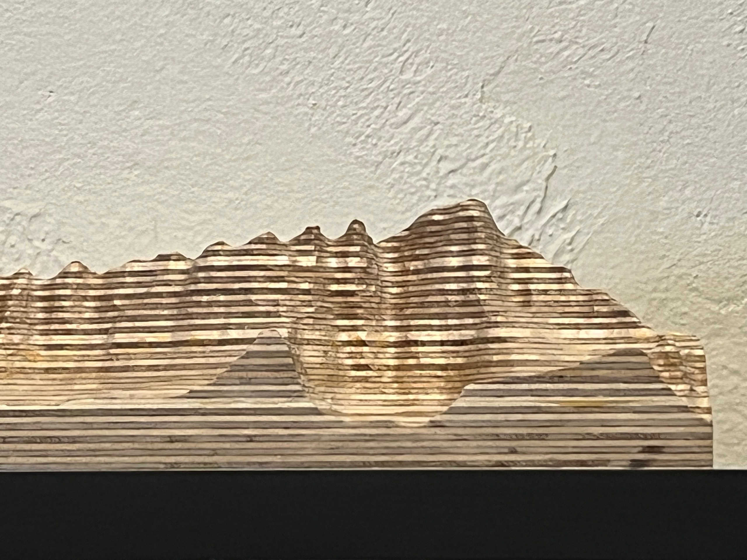
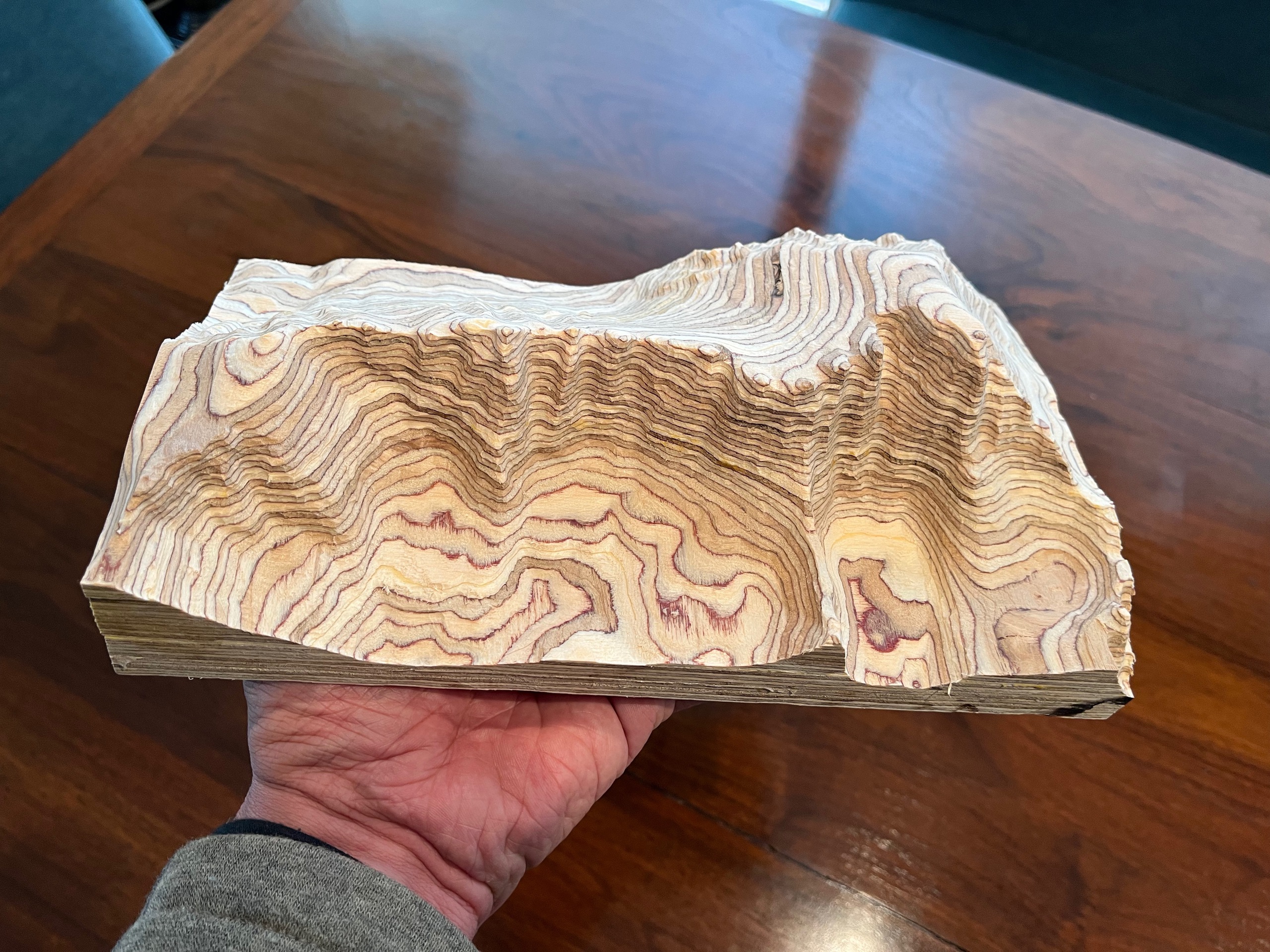
My wife and I met hiking to the top of Mt Whitney in 1996 and I made this 1:12000 scale model, cut out of Birch plywood on a CNC router, for our 25th anniversary. I love how the layers in the plywood show the contour lines (at this scale each 1/16 inch layer is 62.5 feet in elevation). I generated the CNC code myself, directly from USGS elevation data, using Python.
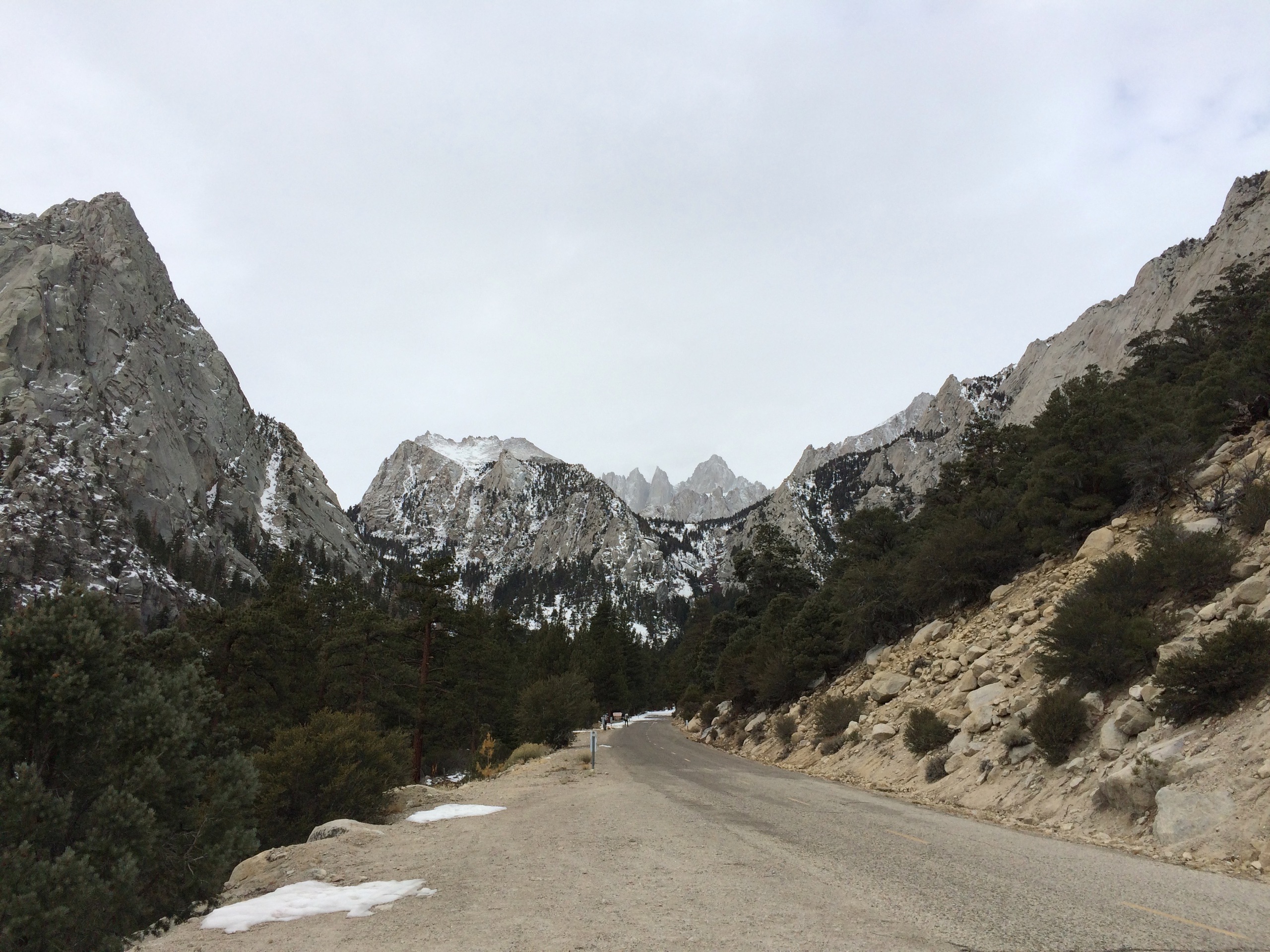
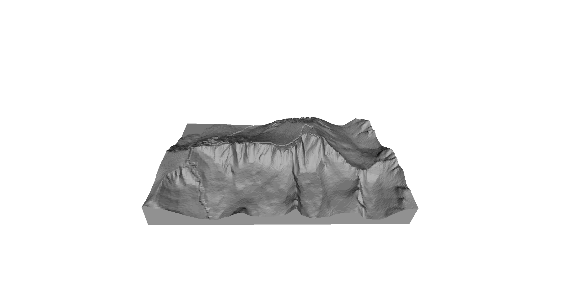
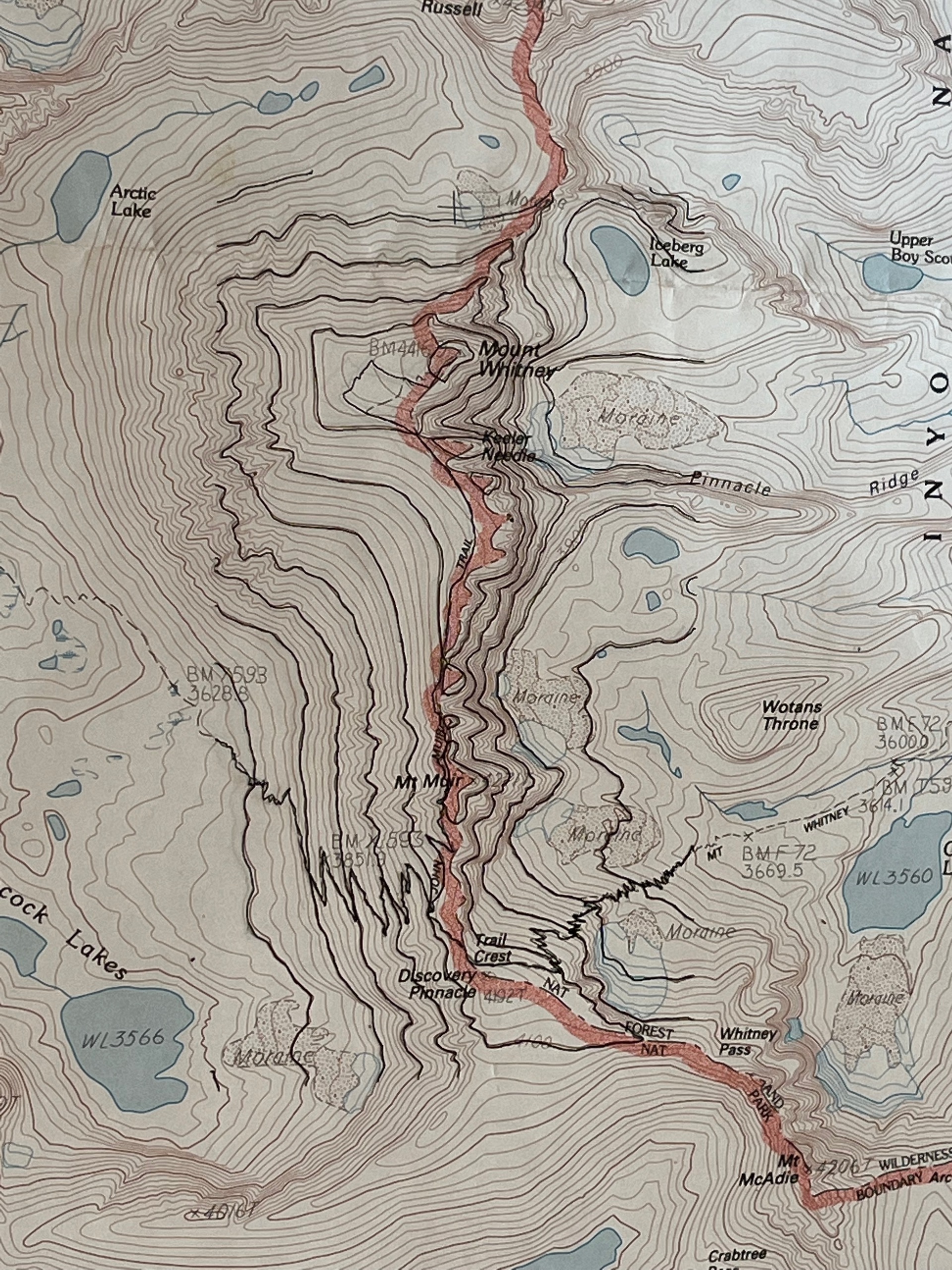
This view, looking west, is what you see as you hike in from the Whitney Portal trailhead.
The trail climbs up the bowl on the left, via a bunch of switchbacks, and then goes along the back side of the ridge to the summit. It's 10.7 miles from Whitney Portal, at 8,360 feet, to the summit at 14,494 feet (or 14,505 feet depending on who you ask).
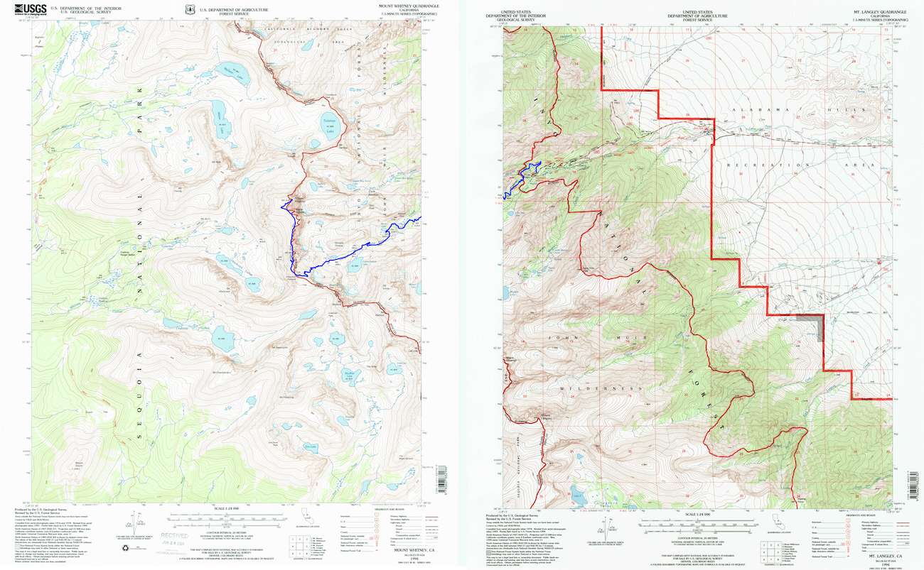
The route covers two quadrangles in the USGS 7.5 minute 1:24000 scale topographic map series, Mt Whitney and Mt Langley.


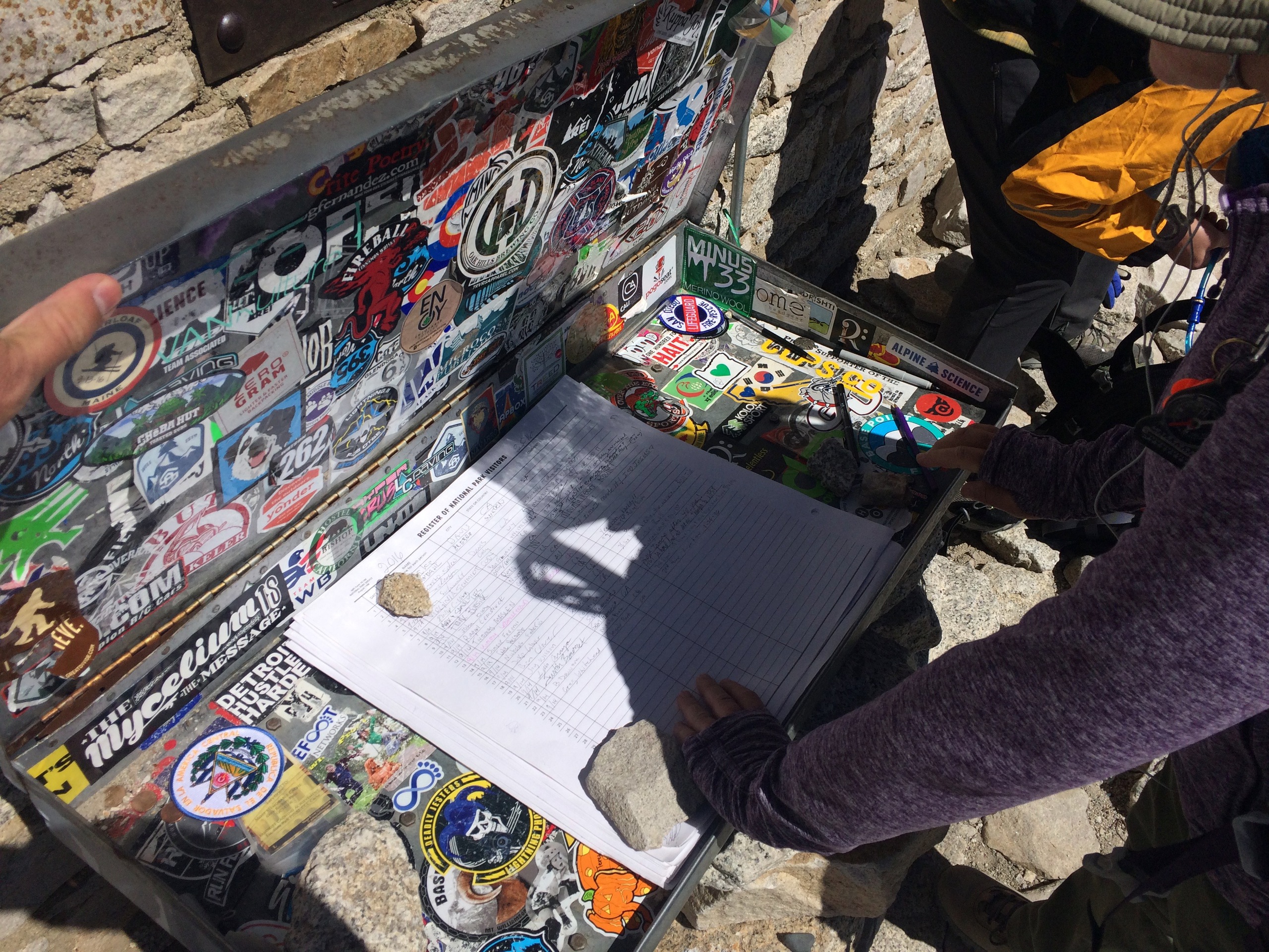

We've hiked to the top of Mt Whitney twice. First in 1996, when we met, and again twenty years later in 2016 (when these photos were taken). Both times we left Whitney Portal before sunrise, hiked to the summit, spent an hour or so taking pictures and signing the log book, and then retraced our steps back, finishing after dark. It's a long day!
The Build
I knew nothing about downloading or working with USGS data when I started this project. I didn't own a 3D printer or a CNC router and I had very little experience with CAD/CAM. It was definitely a learning experience!
A build in three acts:
- Act I (USGS Data, 3D Printing, CNC Milling)
- Act II (GIS Coordinates, Birch Plywood)
- Intermission
- Act III (Scaling Up)
- Coda
OMG TL;DR --> SKIP TO THE END <--
Act I (USGS Data, 3D Printing, CNC Milling)
Sept 2019
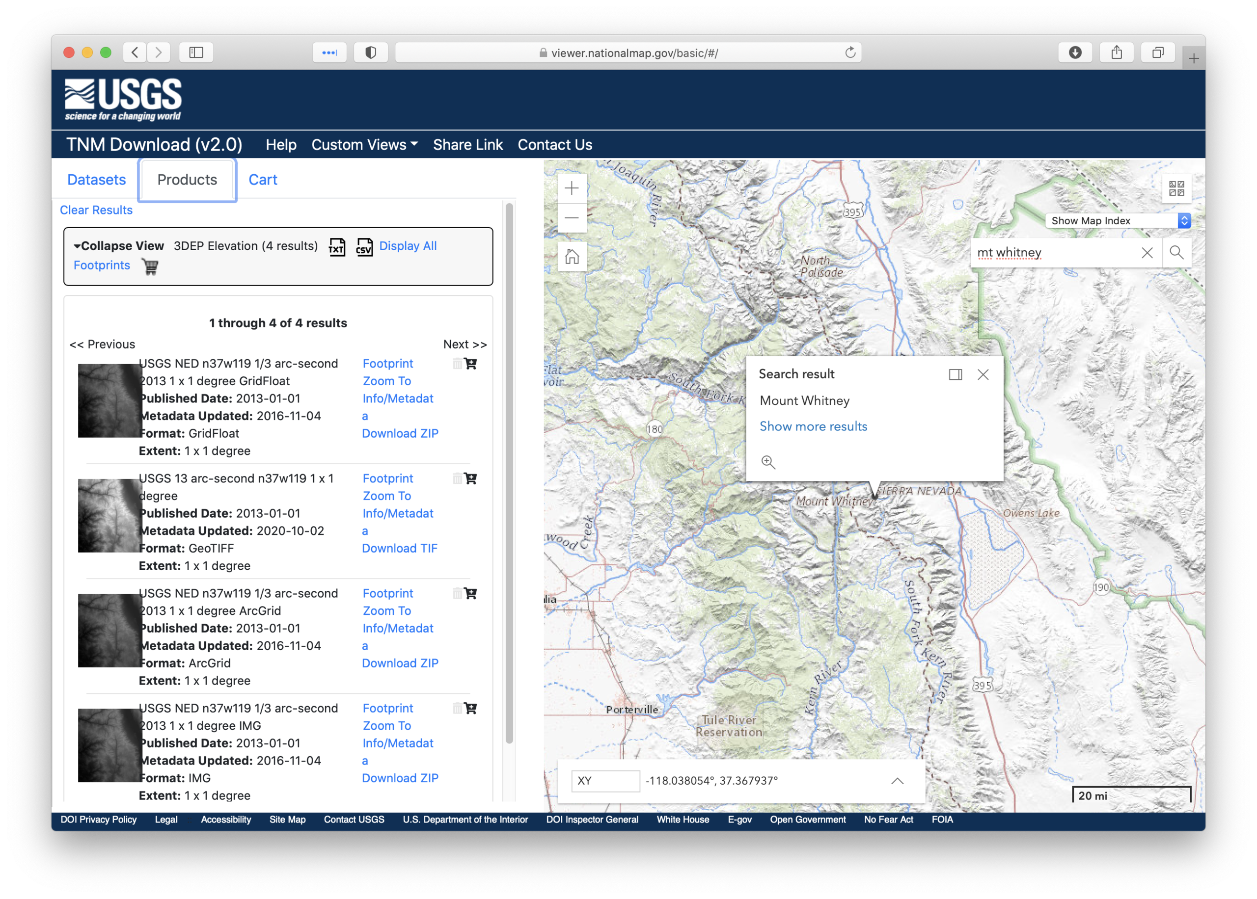
I downloaded the elevation and trail data for the Mt Whitney area from The National Map. The elevation data comes from the USGS and has data points every 1/3 arc second (about 10 meters).
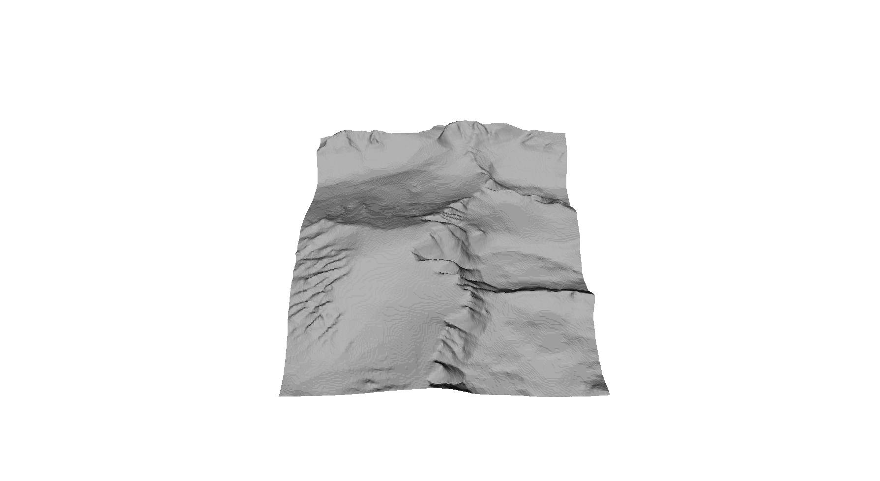
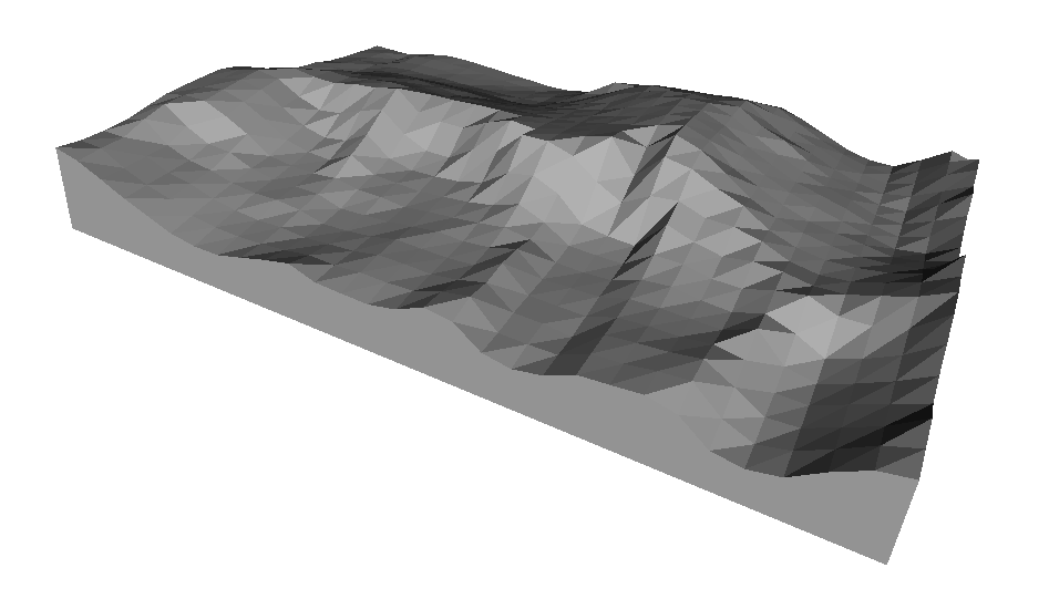
I used the open source Geospatial Data Abstraction Library (GDAL) to process the data and, with a bit of code that I found on stackexchange gdal_rastertotrn.py, was able to turn the elevation data into a trianglar mesh surface that could be rendered in 3D.
With a little more work I added the trails and turned the surface into a 3D model. Now I just needed to figure out what to do with it!
Feb 2020
Finally having an excuse to buy a 3D printer, I got an Ender 3 Pro.
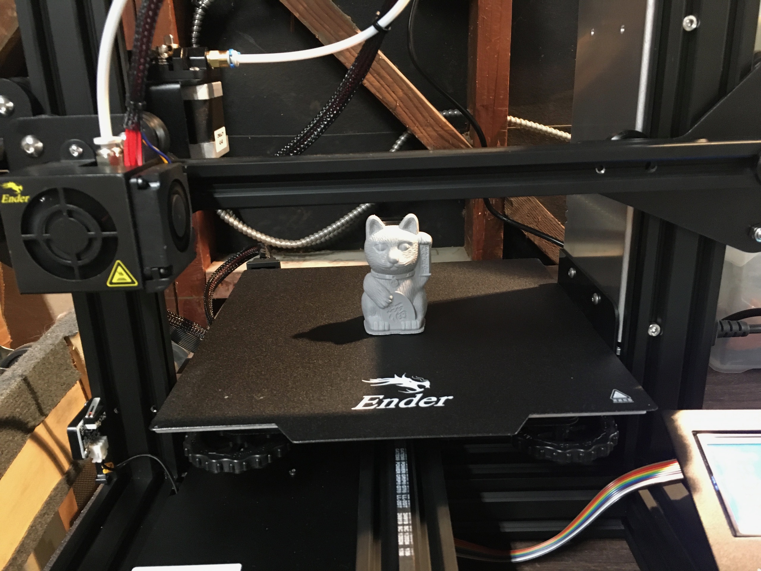
After setting it up and printing the included Maneki-Neko (Beckoning Cat) test file I was ready to try the Mt Whitney model.

I used Ultimaker Cura to slice the model and generate the GCode file for the printer. This was only the second thing I had ever 3D printed and it worked flawlessly the first time, a testament to how mature 3D printing tools are (as compared to CNC milling tools, as you'll see below).
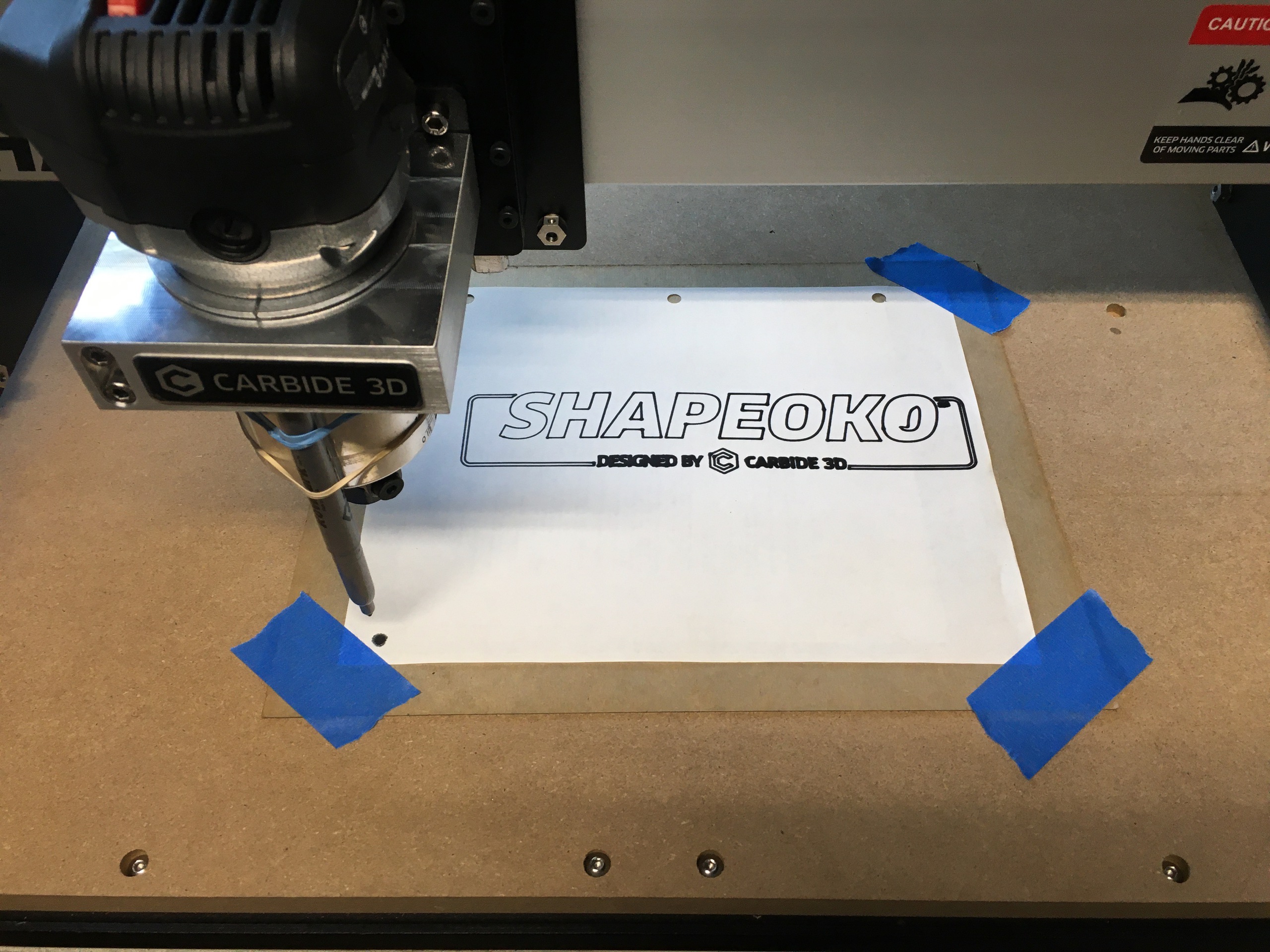
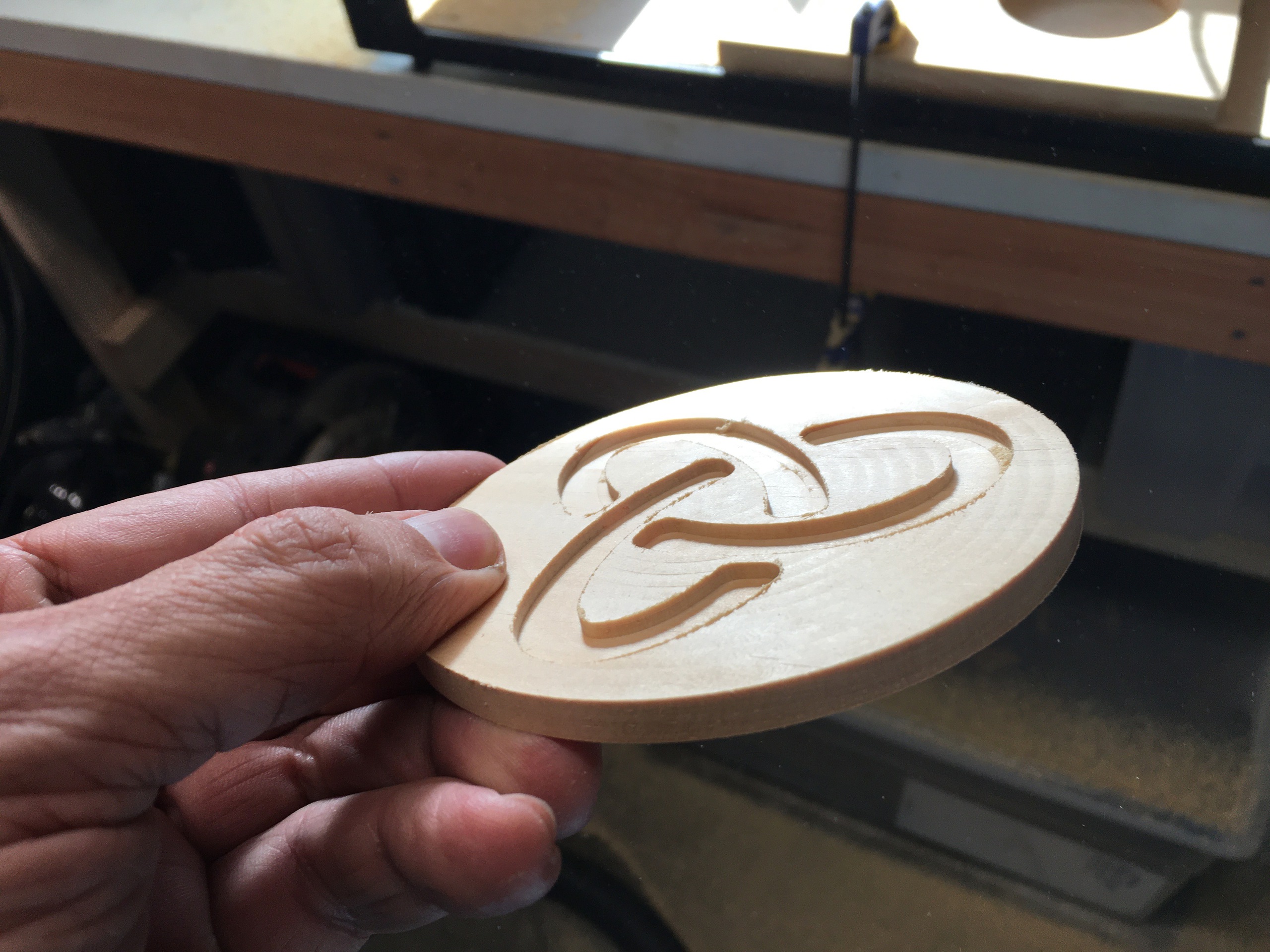
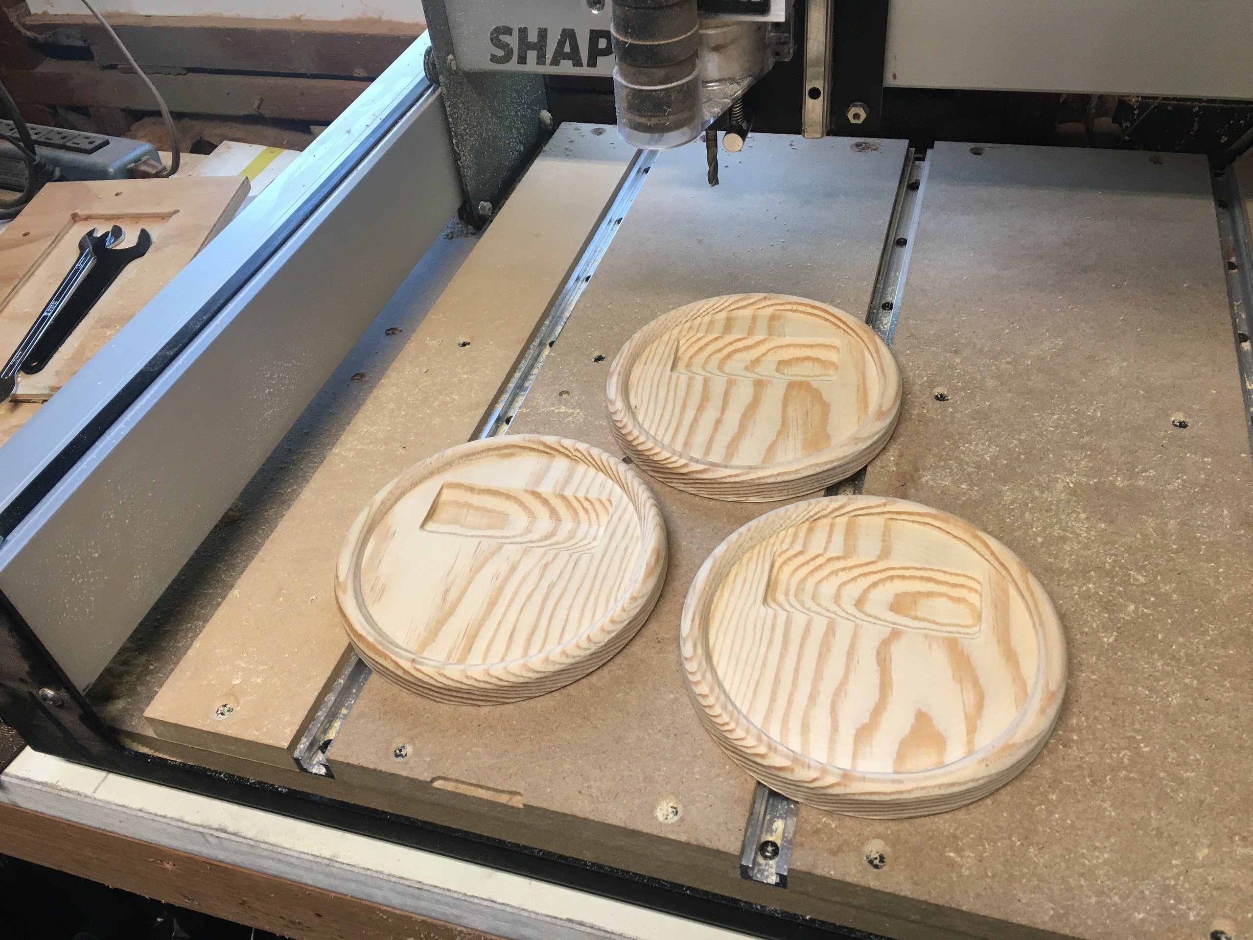
Emboldend by my success with 3D printing, I bought a Shapeoko 3 CNC router with the idea cutting the Mt Whitney model out of wood. I had some experience with CNC routers from TechShop, before they went out of business, and from a friend who had one at work, but it was still a steep learning curve compared to 3D printing. I started with a simple coaster project using Carbide Create, bundled with the Shapeoko 3.
With my CNC router working, I started looking at how to cut the Mt Whitney model on it. I needed to generate GCode that would run on the CNC, a process similar to slicing for a 3D printer, but a lot more complicated.
I evaluated a bunch of tools, including Fusion 360, but didn't find anything that was affordable, easy to learn, and could handle my high resolution 3D model without slowing to a crawl. I'm sure this was mostly my fault, not knowing what I was doing, but there I was.
May 2020
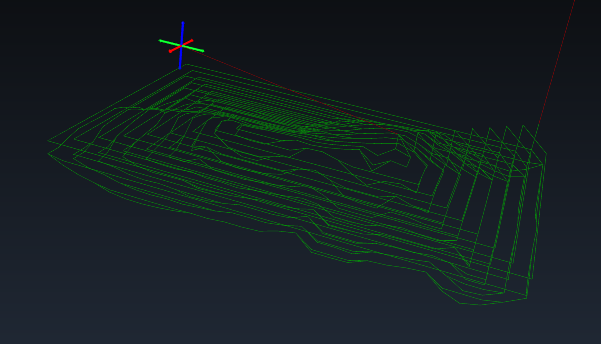
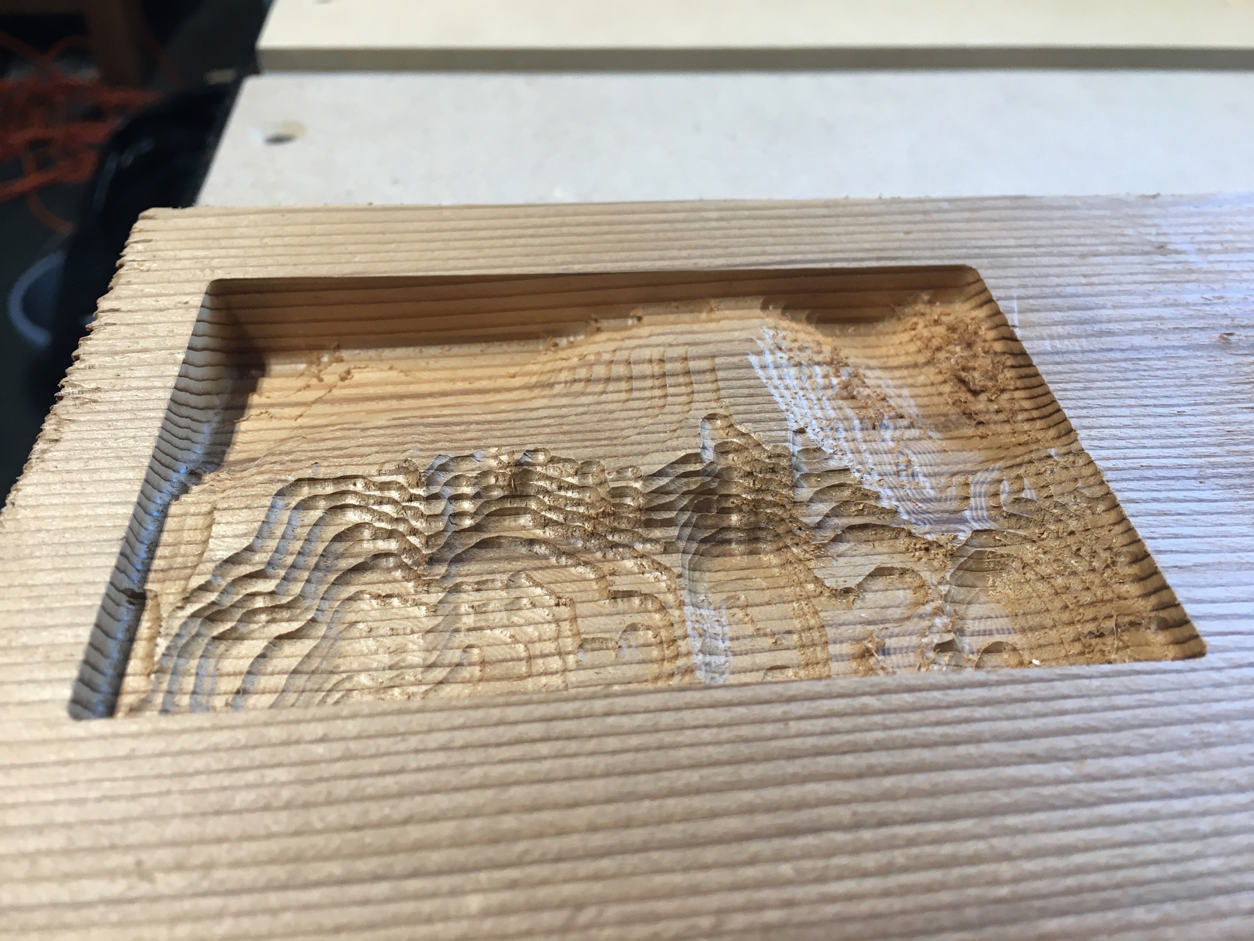
Frustrated, I started experimenting with generating GCode myself with Python. This was my first low resolution experiment. The toolpath and model were both generated directly from the elevation data, with the model just being used for visualization. I ran the GCode on my CNC and cut some scrap wood with a 1/4 inch bit. It doesn't look like much, but you have to start somewhere.
My next experiment was double the resolution, cut with a 1/8 inch bit.

At this point I decided to give Fusion 360 another try with a lower resolution model. I was able to generate a nicer toolpath, cutting along contour lines, but it was still painfully slow and I was having more fun writing my own code.
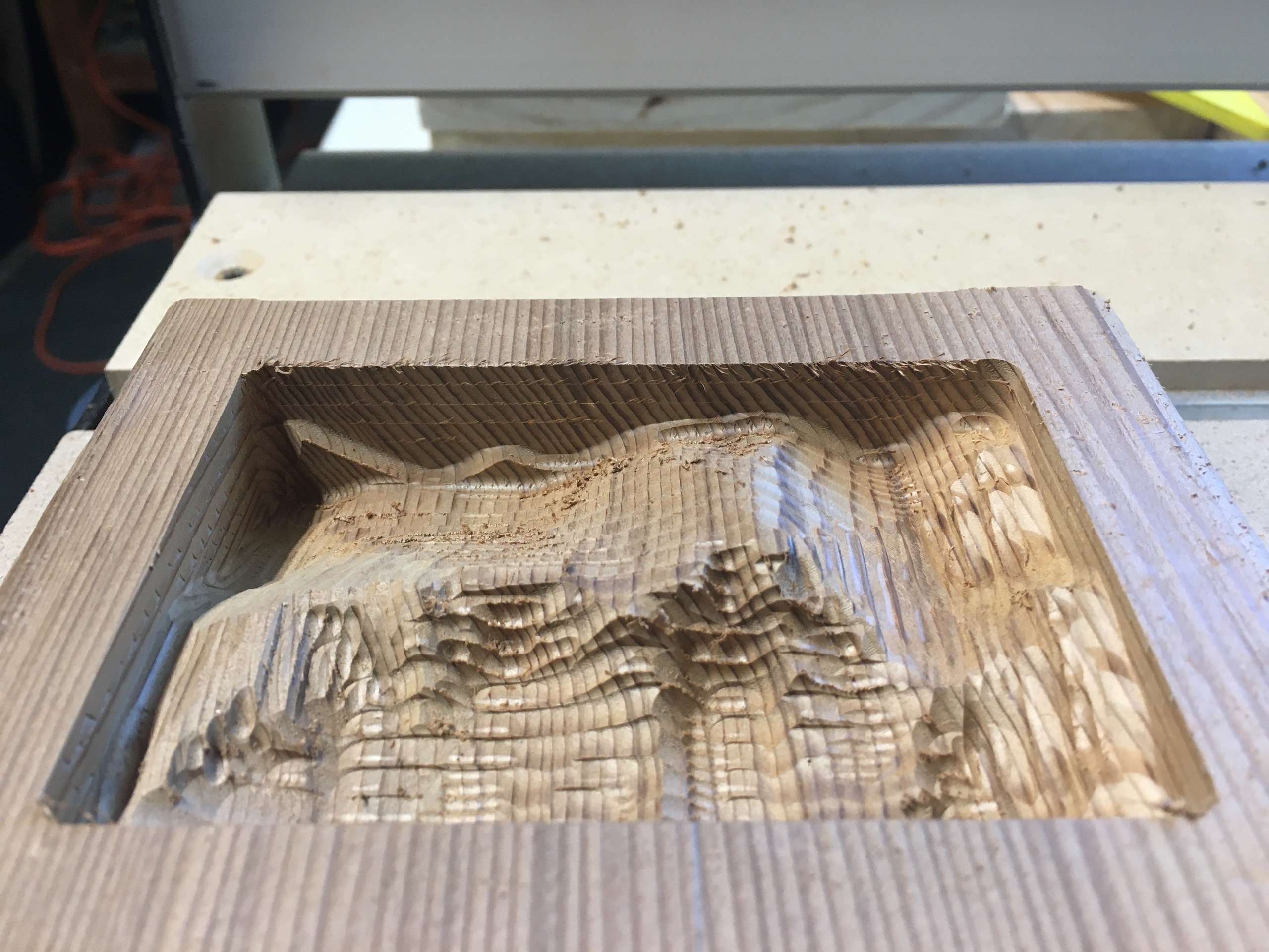
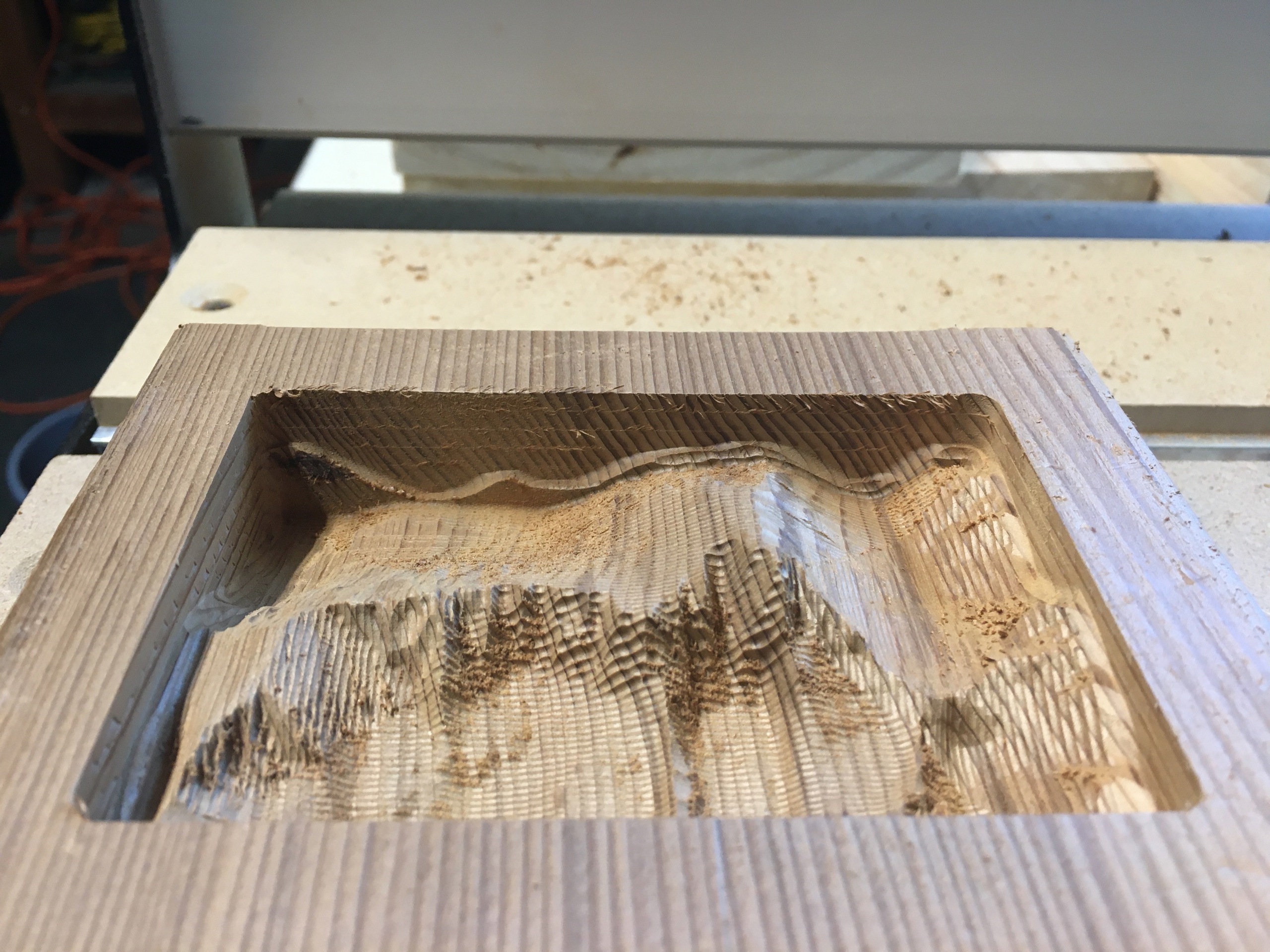
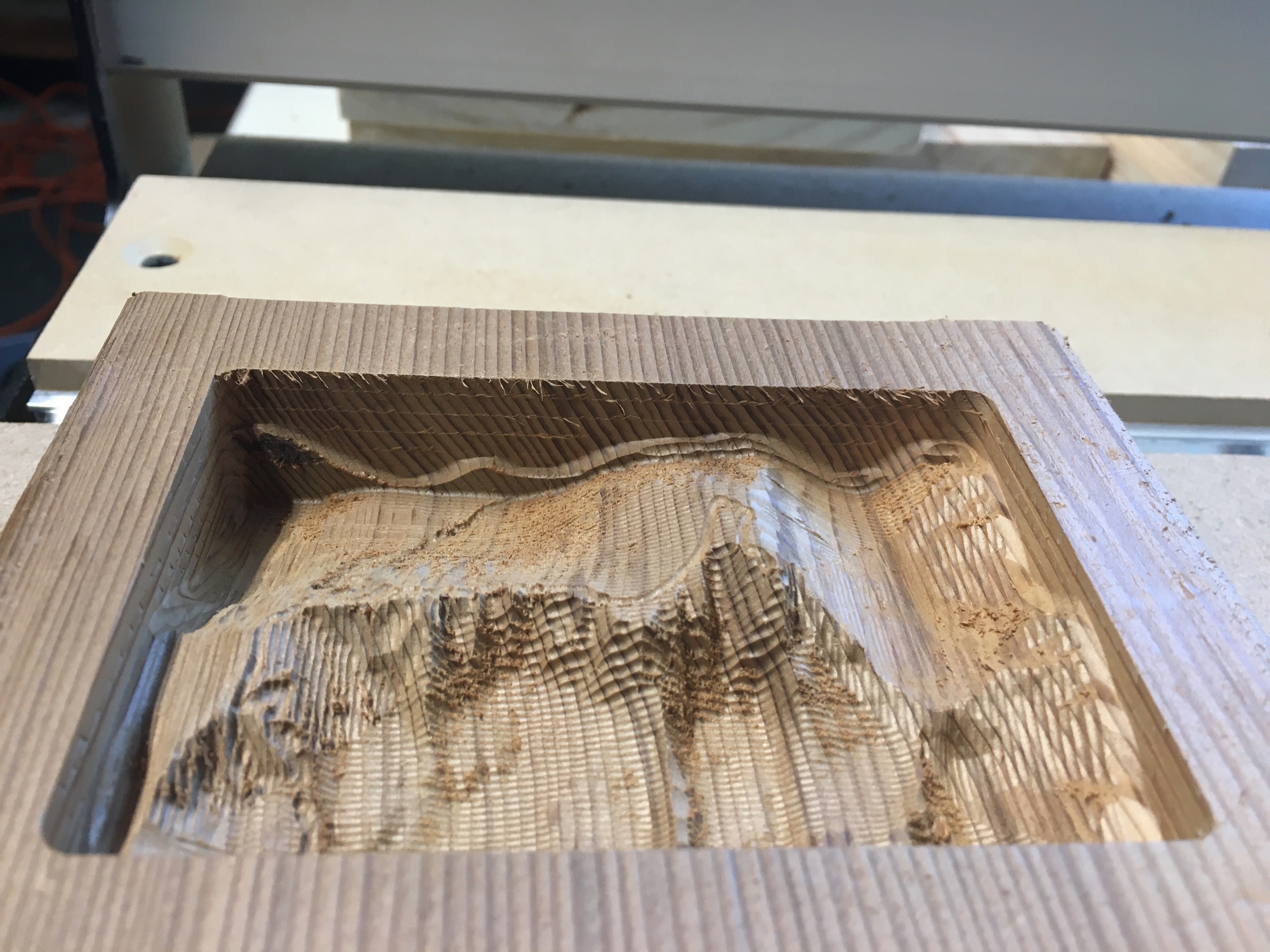
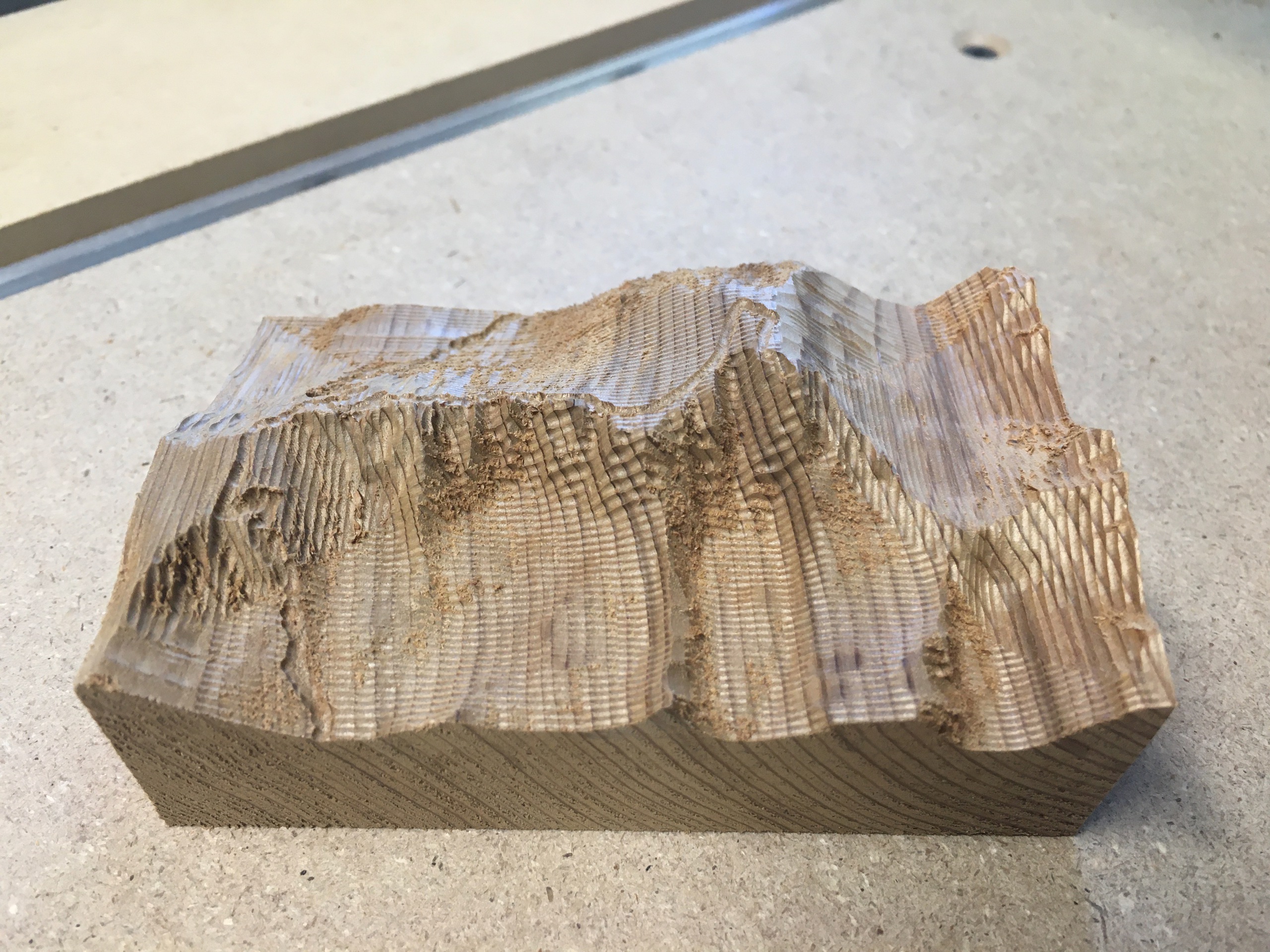
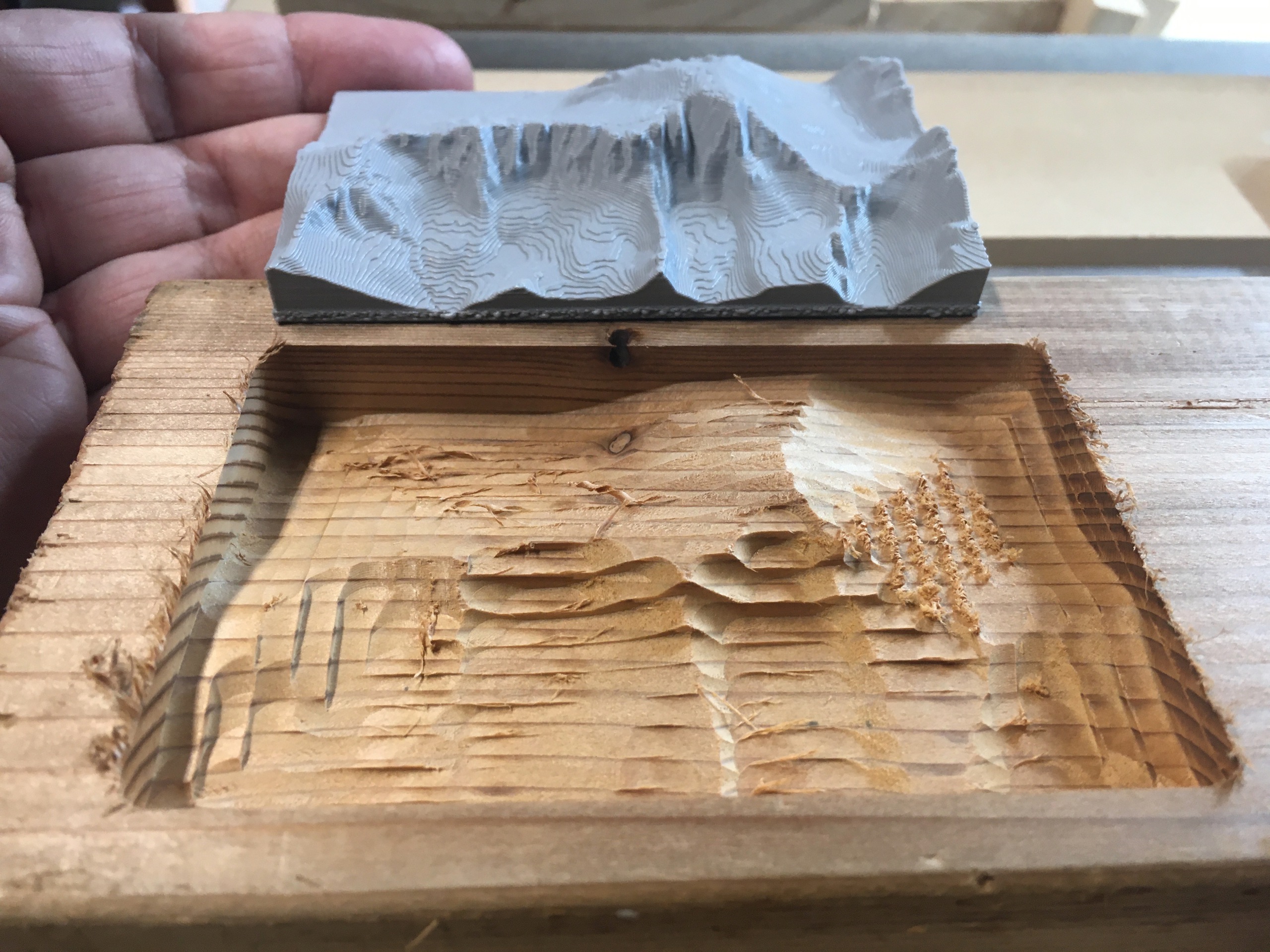
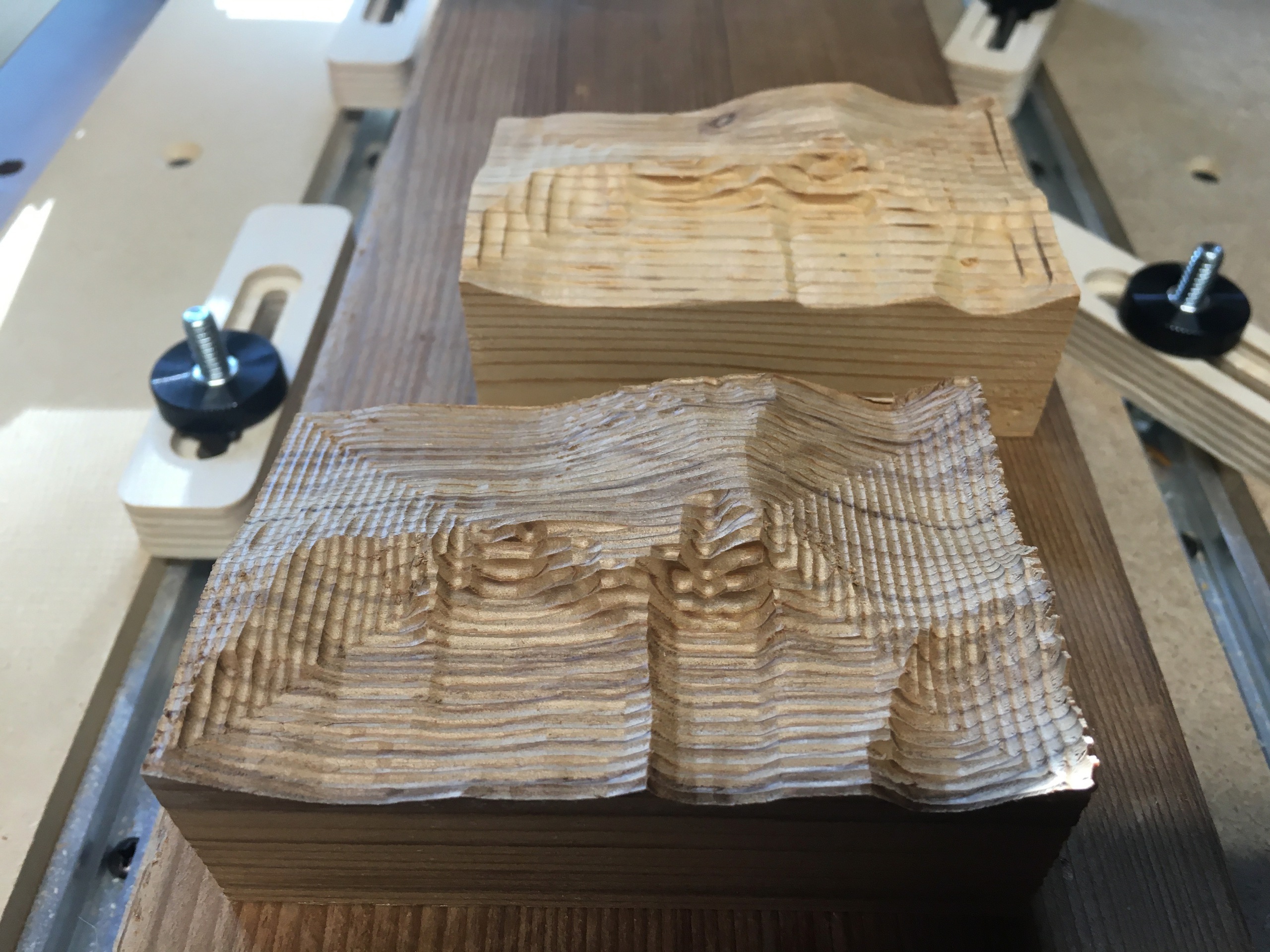
Back to writing my own code, I doubled the resolution again and split the job into multiple passes: a first pass to rough out the shape with a 1/4 inch bit, a second pass to add detail with a 1/16 inch, and a third pass to cut the trails. Total cutting time about 2 hours.
Confident in my approach, I started thinking about cutting a larger version with a smoother surface finish in a nicer (harder) wood. All of these things would increase cutting time:
- a larger model would have more material to cut
- a smoother surface finish would require more overlap between passes with the cutter
- a harder wood might require a shallower depth-of-cut to control the forces on the machine
To scale up to the size I wanted, big enough to look impressive on our mantle, I was going to have to push the machine to its limits and optimize my code as much as possible.
I had also just discovered that the features on my model were distorted relative to the USGS topo map we used on our hike. I was about to learn about GIS coordinate systems!
Act II (GIS Coordinates, Birch Plywood)
August 2020
The USGS topo map we used on our hike, that I wanted my model to match, was from the USGS 7.5 minute 1:24000 scale topographic map series. It covers 7.5 minutes of lattitude from 36°30′00″N to 36°37′30″N, and 7.5 minutes of longitude from 118°22′30″W to 118°15′00″W. Mt Whitney is at 36°34′43″N 118°17′31″W
The USGS elevation data that I was using was in the North American Datum (NAD83) coordinate system, where the distances between lines of lattitude and lines of longitude are equal, about 69 miles per degree. But the Earth is not flat[citation needed] and lines of longitude converge at the poles! At the lattitude of Mt Whitney, the distance between lines of longitude is only 53 miles per degree. This meant that my model was distorted.
To correct for this distortion, USGS topo maps use the Universal Transverse Mercator (UTM) coordinate system. Mt Whitney in in UTM Zone 11. I used the GDAL tools to convert the elevation data from NAD83 to UTM11 and I was back in business.
With the elevation data corrected I needed to reframe my model. I checked the new model area by printing it on a transparency at 1:24000 scale and overlaying it on the map. Perfect!
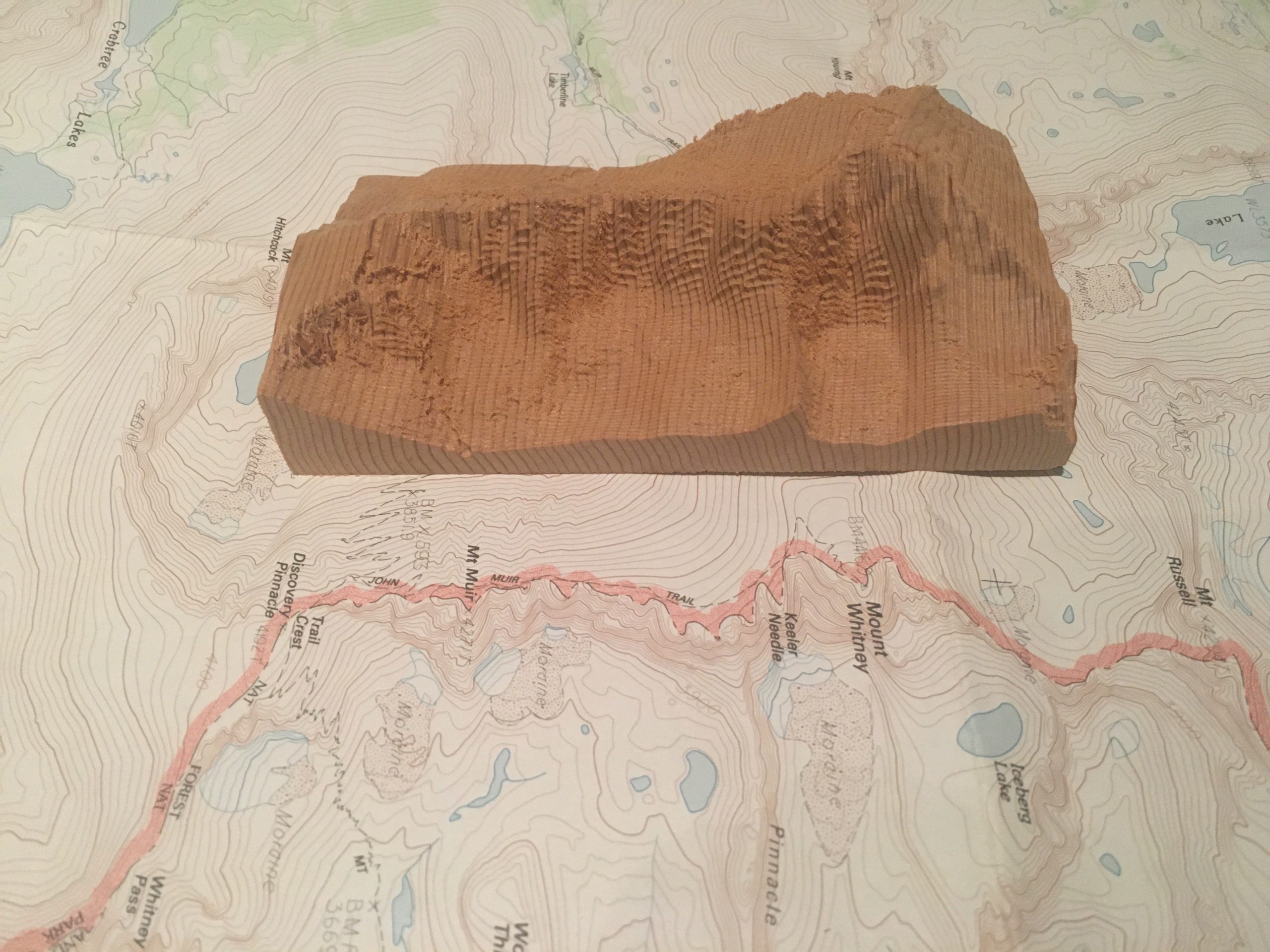
I cut the new model, measuring 3 x 5.25 x 1.5 inches at 1:24000 scale, in some more scrap wood. It lined up perfectly with the map!
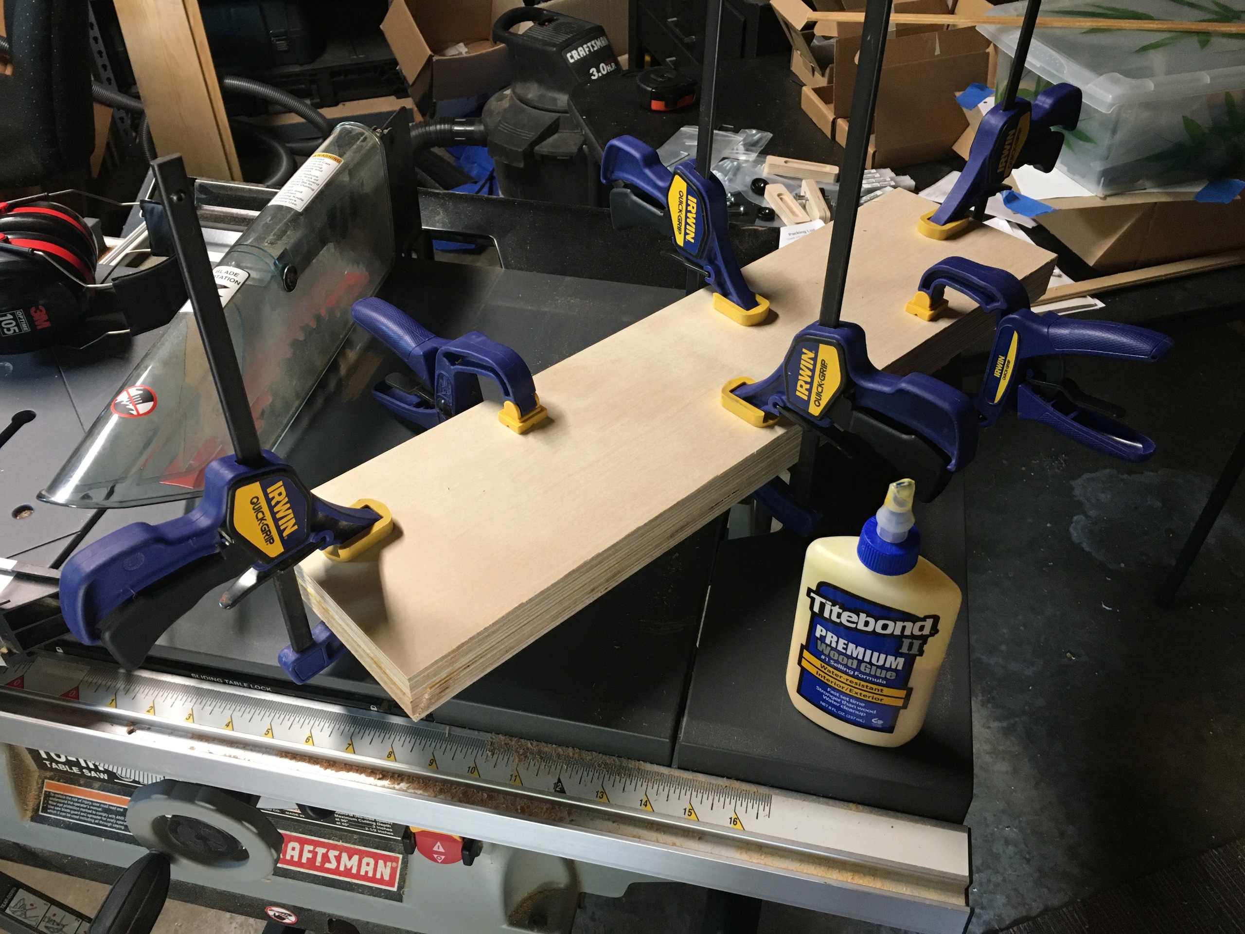
I was finally ready to cut some nicer wood! I decided to try Birch plywood, hoping that the layers would highlight the contour lines. I had to glue up two 3/4 inch layers to get the thickness I needed.
I was still learning about CNC feeds and speeds, parameters that determine the quality and speed of a cut with a particular bit in a particular material, and depth and width of cut, additional parameters that determine the engagement of the bit in the material. Together these parameters determine the force on the bit as it cuts.
I had set the cutting parameters conservatively for the relatively soft wood used in my initial experiments, and everything I read said they were still within spec for the harder Birch plywood. This would be great if true, since cutting time wouldn't increase.
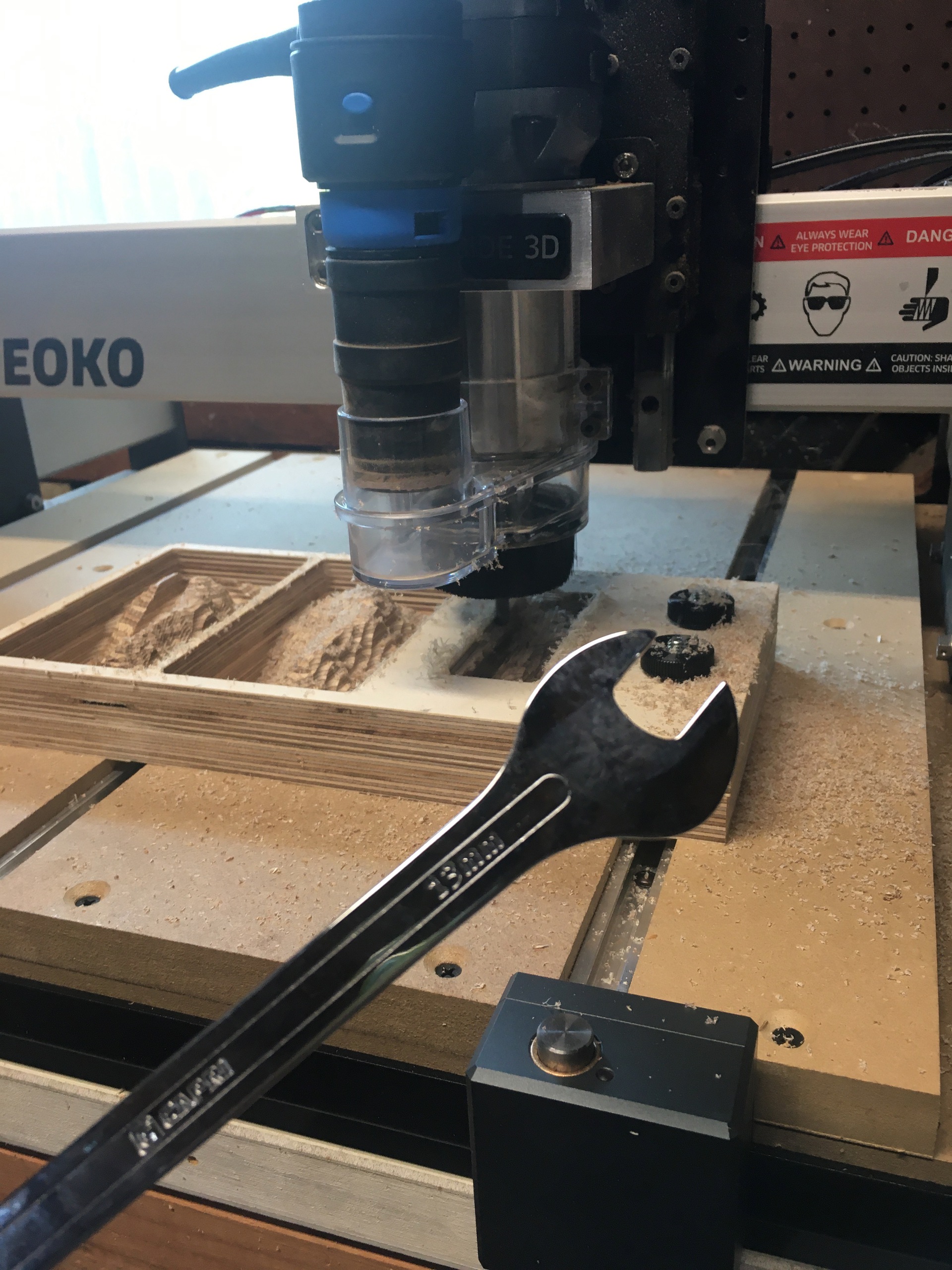


Well, the first cut failed about halfway through when the bit slipped in the collet. Suspicious that the collet might not have been tight enough, I reset the bit and tightened it with more force... enough to deform the cheap stamped wrench that came with my CNC (though honestly it didn't feel excessive). I went ahead and ran a second cut and that failed too. The next day I bought a better wrench, successfully tightened the collet, and the third cut worked flawlessly! Total cutting time about 2 hours.
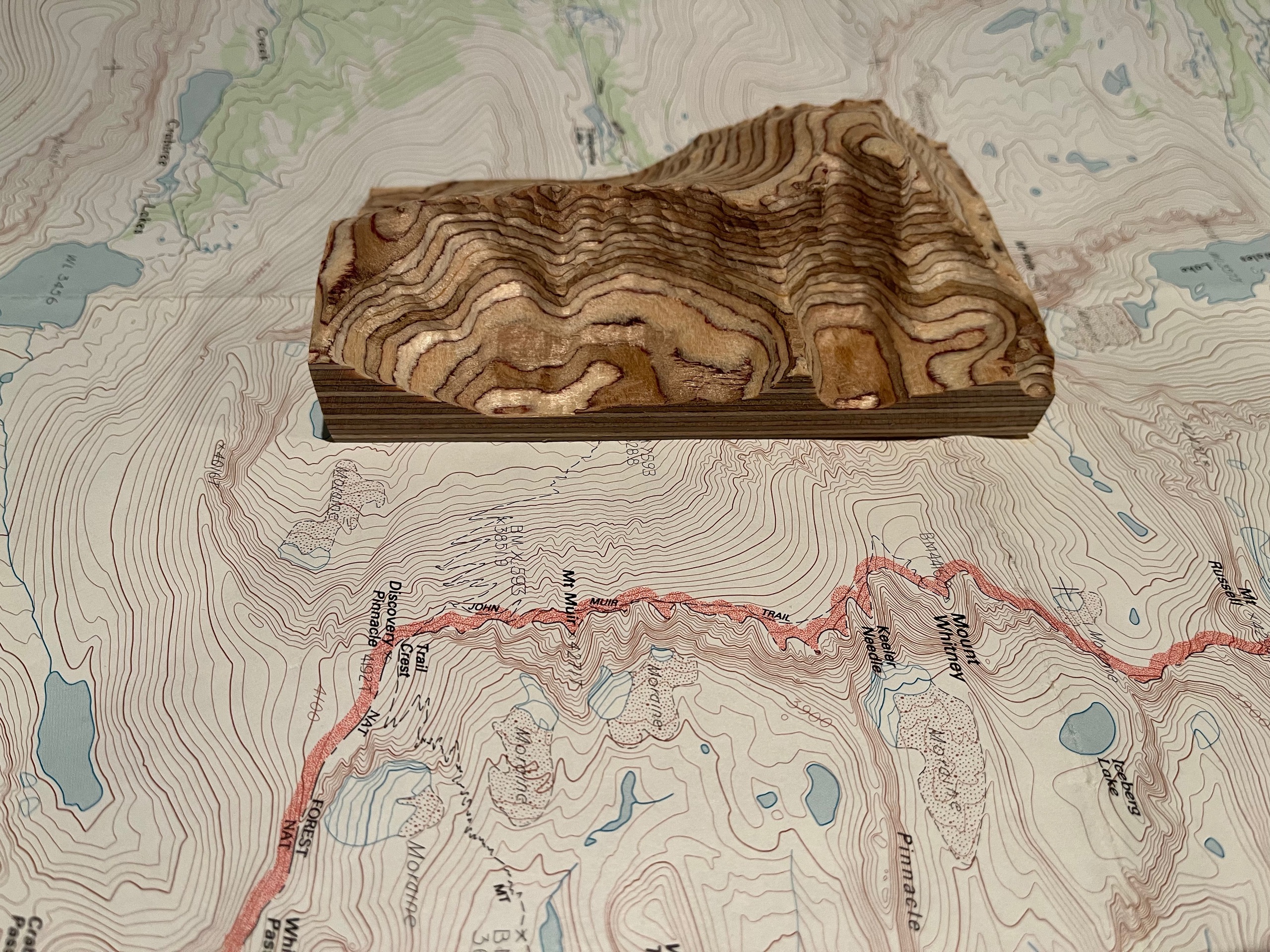
The layers in the plywood highlighted the contour lines just as I had hoped! At this scale each 1/16 inch ply is 125 feet in elevation.
Now I just needed to figure out how to double the size, to 6 x 10.5 x 3 inches at 1:12000 scale, and improve the surface finish. Doubling the size would increase the cutting time to 8 hours and improving the surface finish would likely increase it even more. I had an idea that cutting along contour lines would be an improvement, based on my experiment with Fusion360, so I started thinking about that too.
Intermission
I was having so much fun generating GCode with Python that I started refactoring my code to create a generic Python CNC milling library. My goal was to make it easy to translate manual pocket milling operations into GCode that could be run on the CNC. My vision was something like a programmatic CAD-less CAM system.
Disclaimer: I'm easliy nerd sniped. I don't recommend that you do any of this. Just learn Fusion360 or SolidWorks or whatever and move on with your life.
June 2020


You can do a lot just cutting pockets of different shapes and sizes in different places. Here I cut pockets in a jig to hold both flat and round moulding and then used it to cut pockets in the moulding for neodymium magnets (to make a magnetic scroll hanger).
I used an Apple Newton to design the jig ;-)
Oct 2020
To better understand what my CNC machine was doing, I wrote a GCode parser and interpreter in Python rs274ngc-python3.
Jan 2021

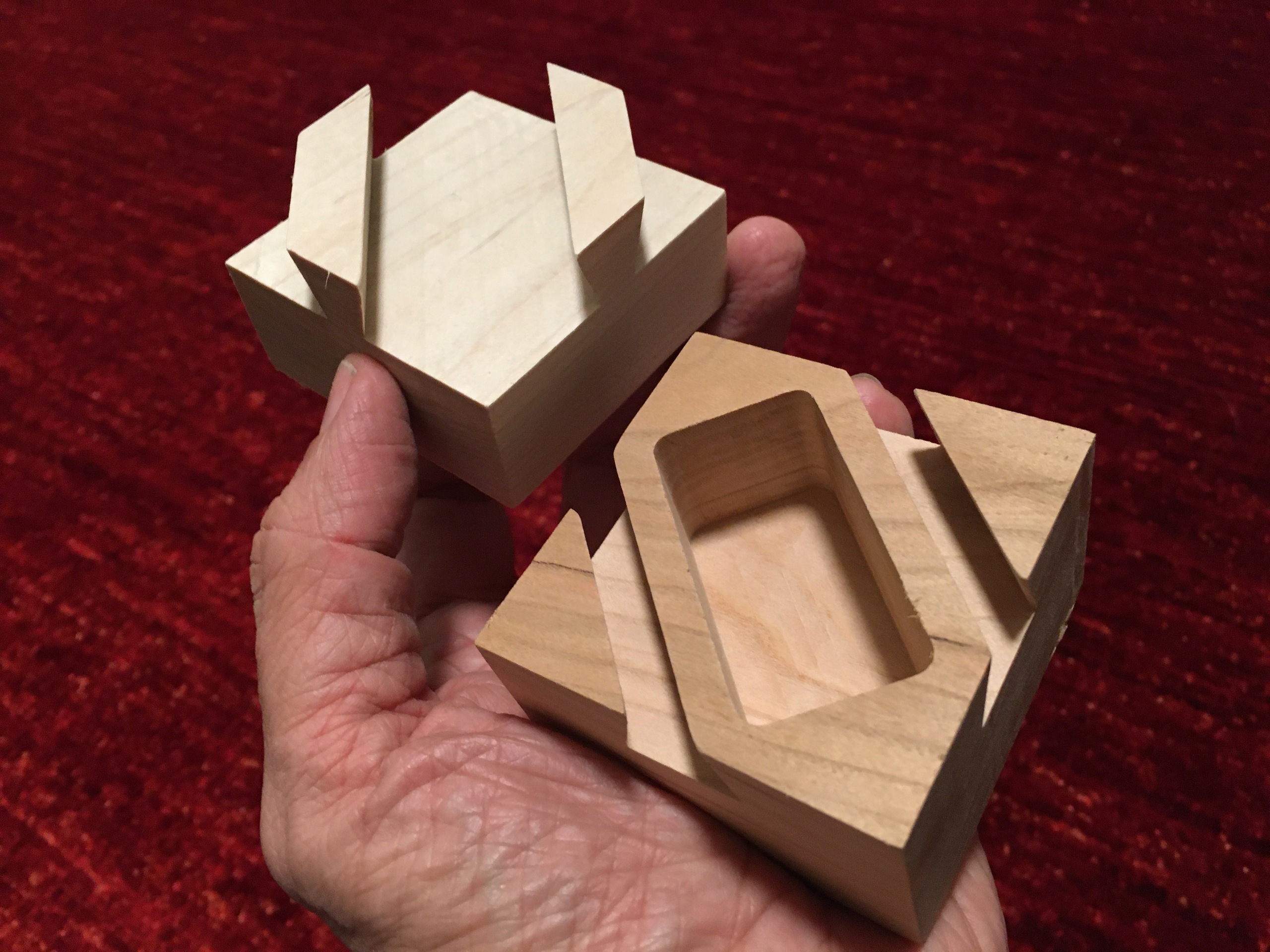
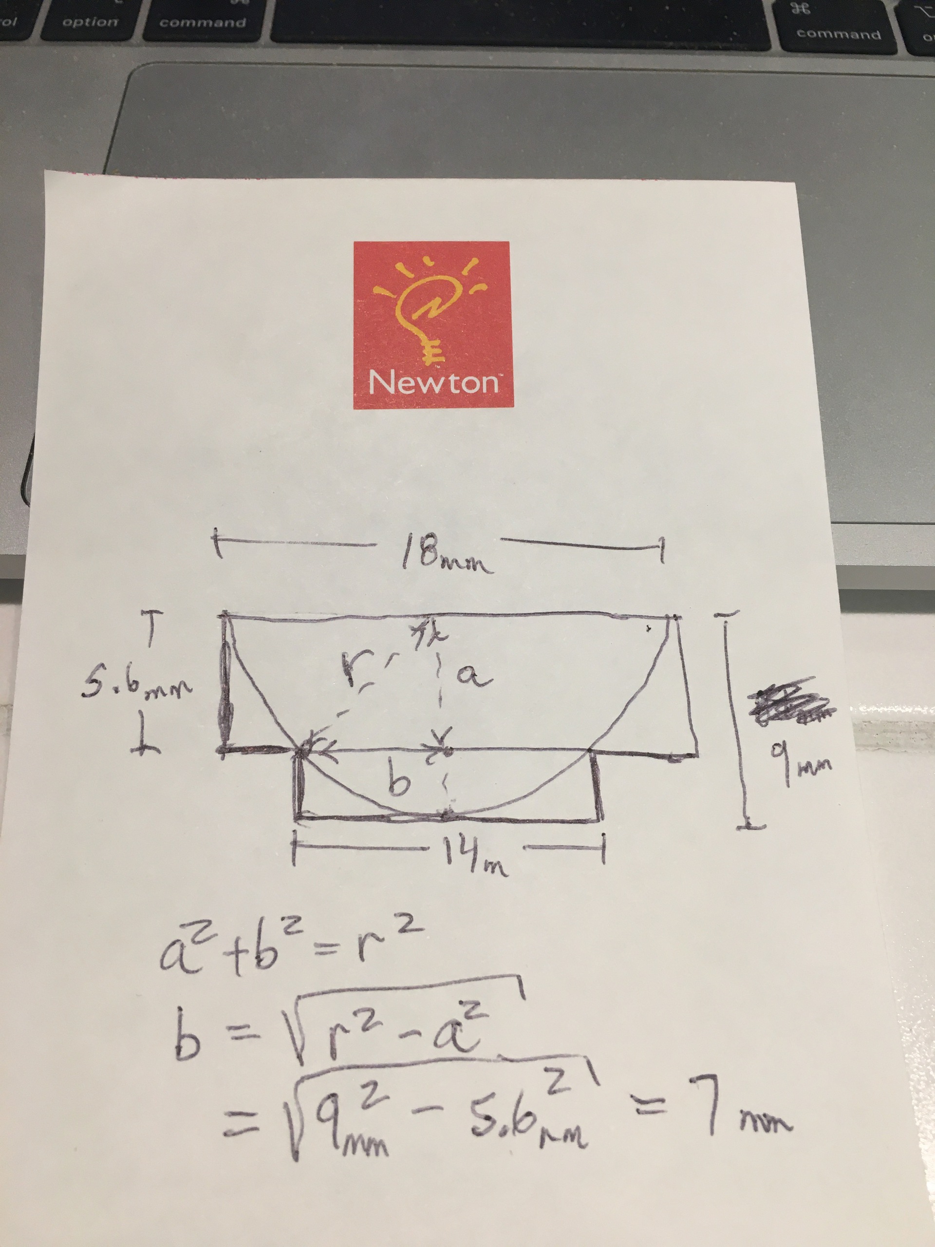
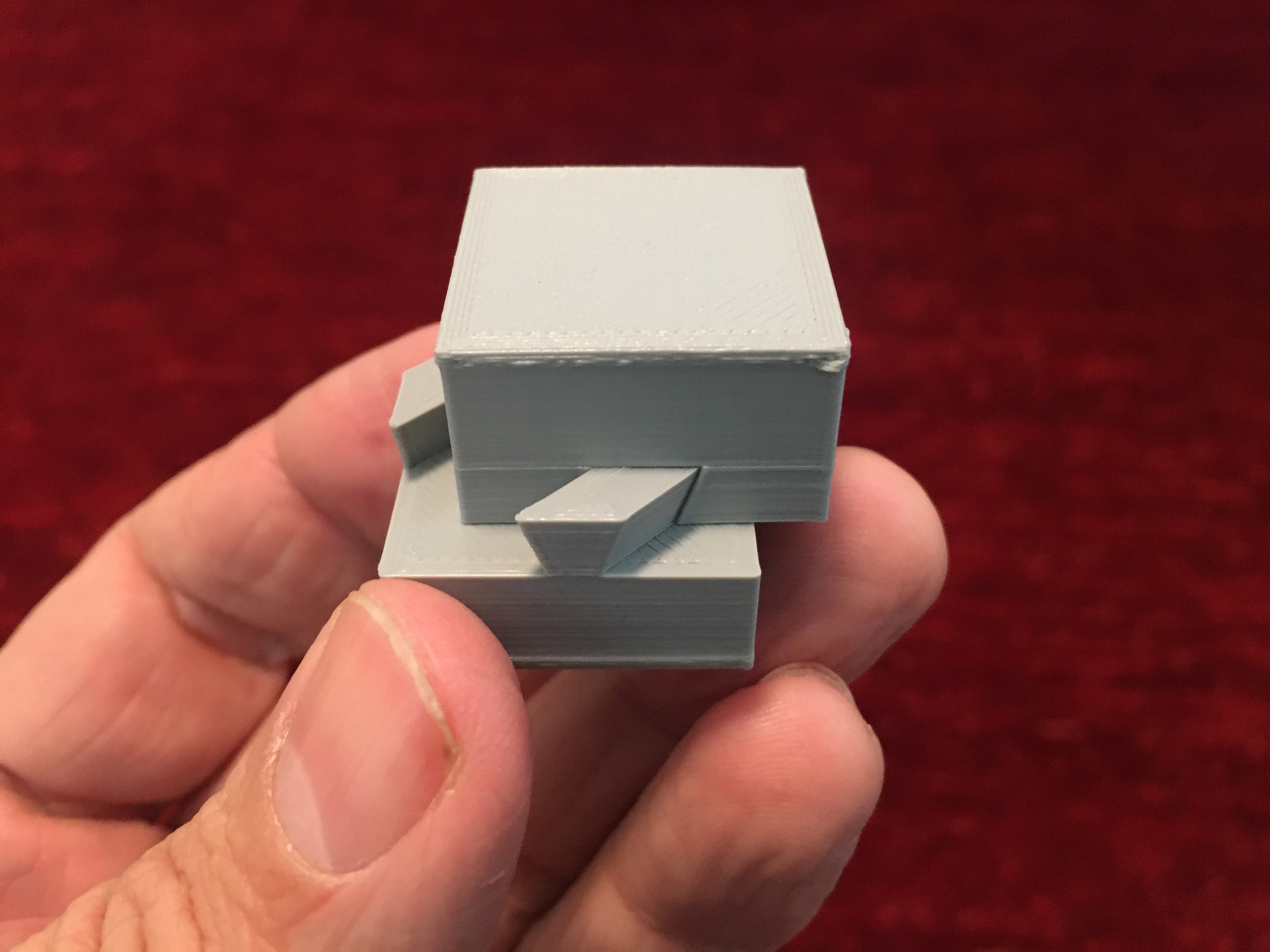
Back to my Python CNC milling library, I added support for profile cuts and made an "impossible" dovetail cube.
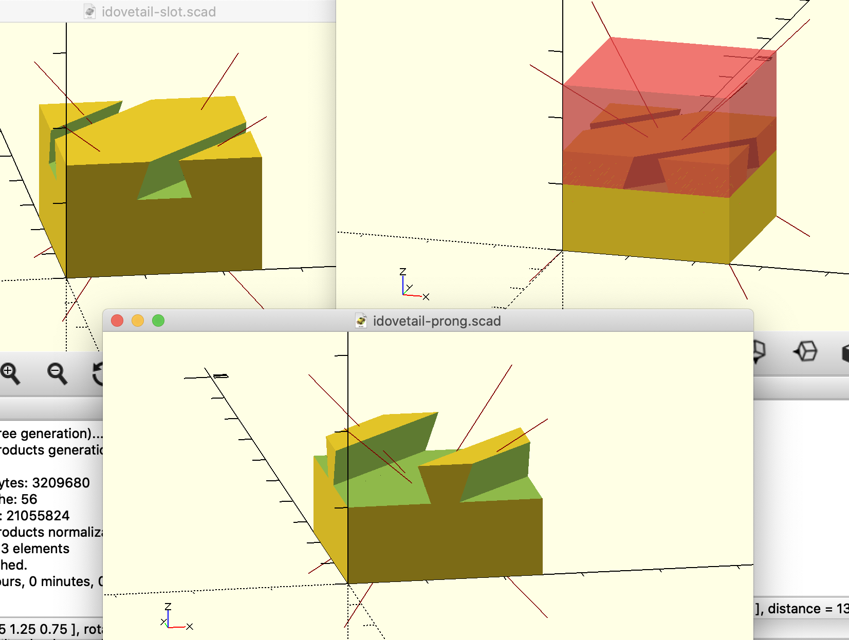
The library can generate OpenSCAD models in addition to GCode. The OpenSCAD models can be used to make 3D prints.
Oct 2021

I added support for radiused pockets and made caster cups for a piano.

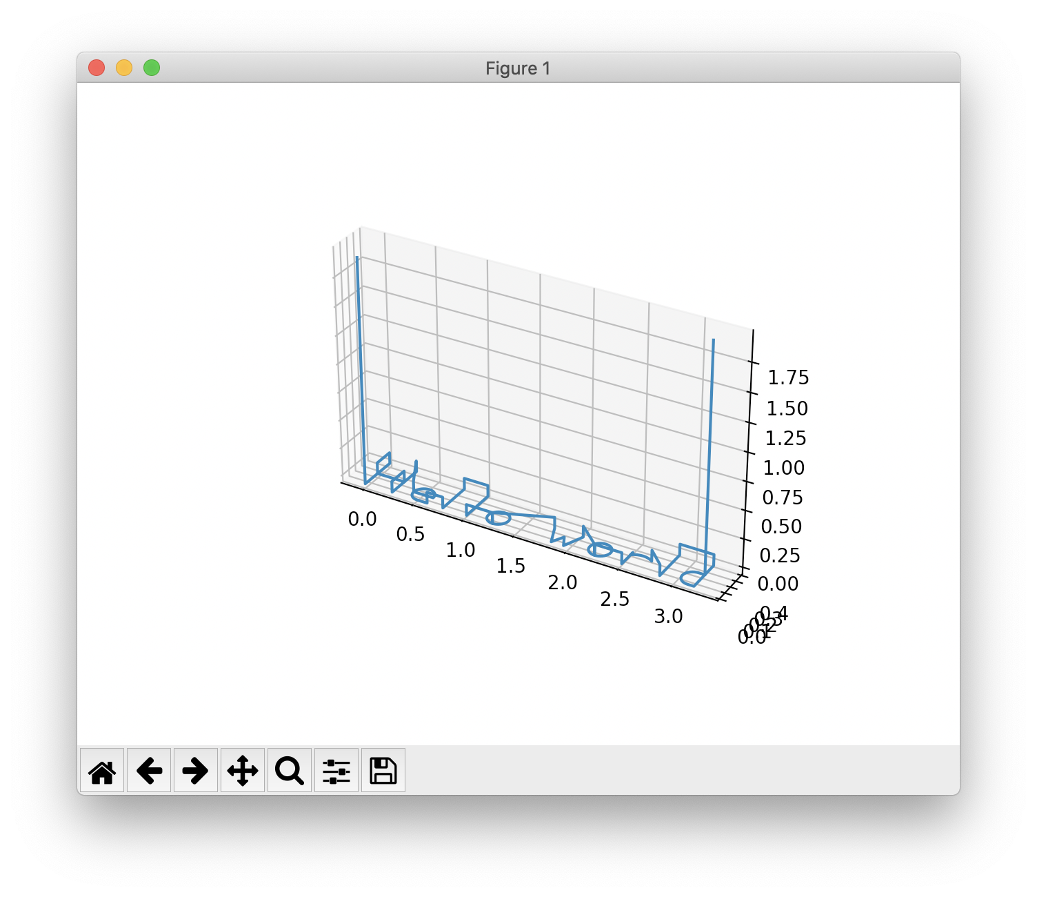
The library can also generate scaled diagrams to help with design.
Apr 2022
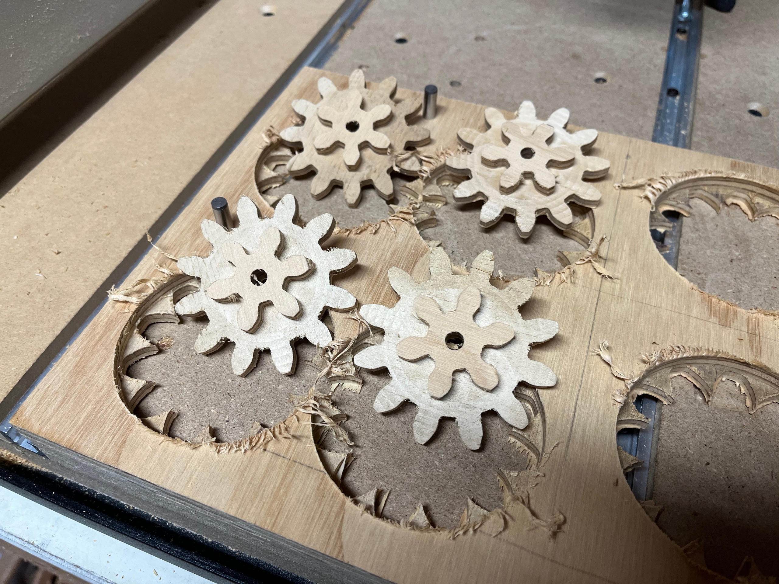
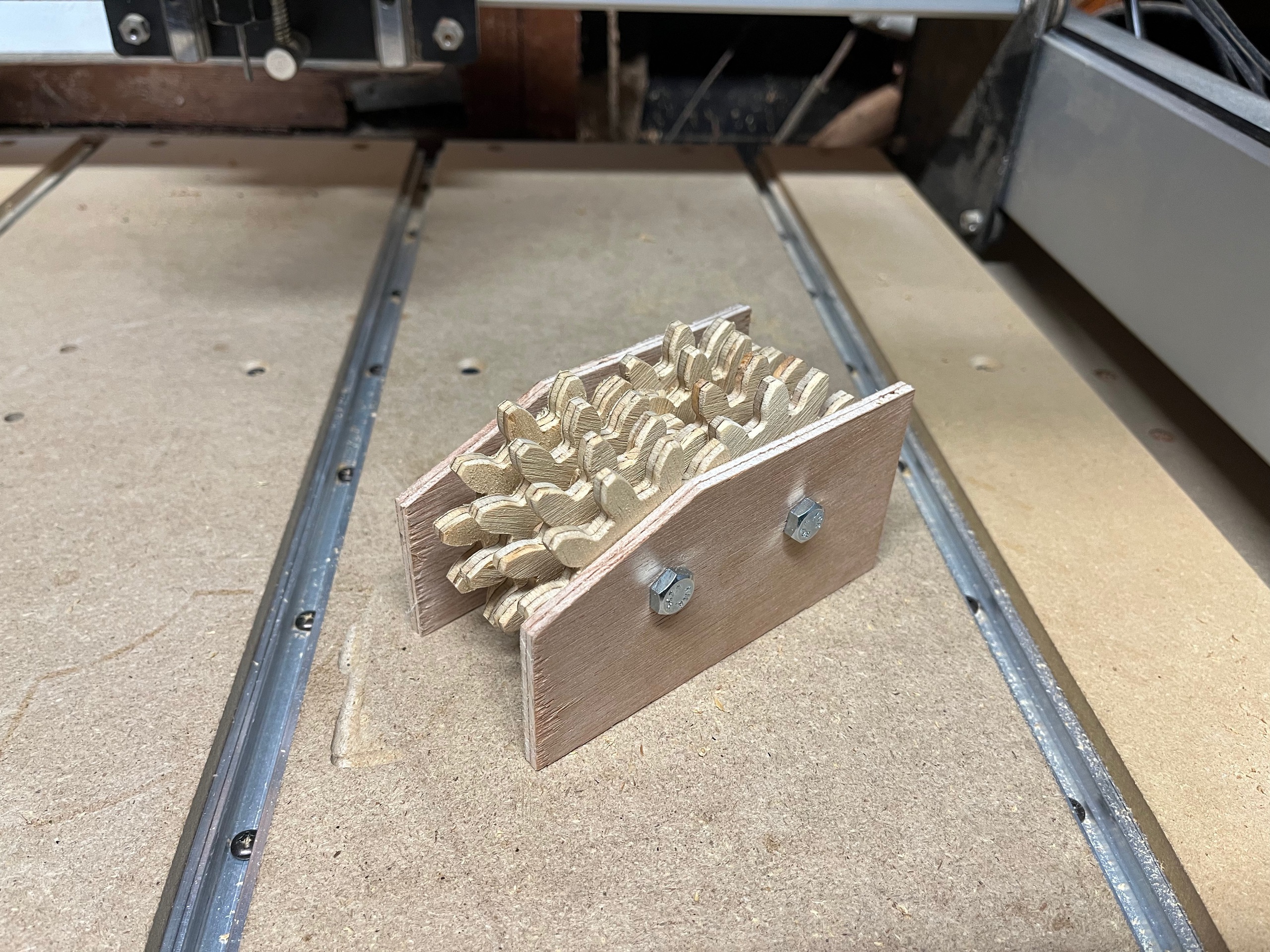
I added support for complex paths like gear shapes and made a 256:1 gear reduction fidget spinner.
Act III (Scaling Up)
Sept 2022
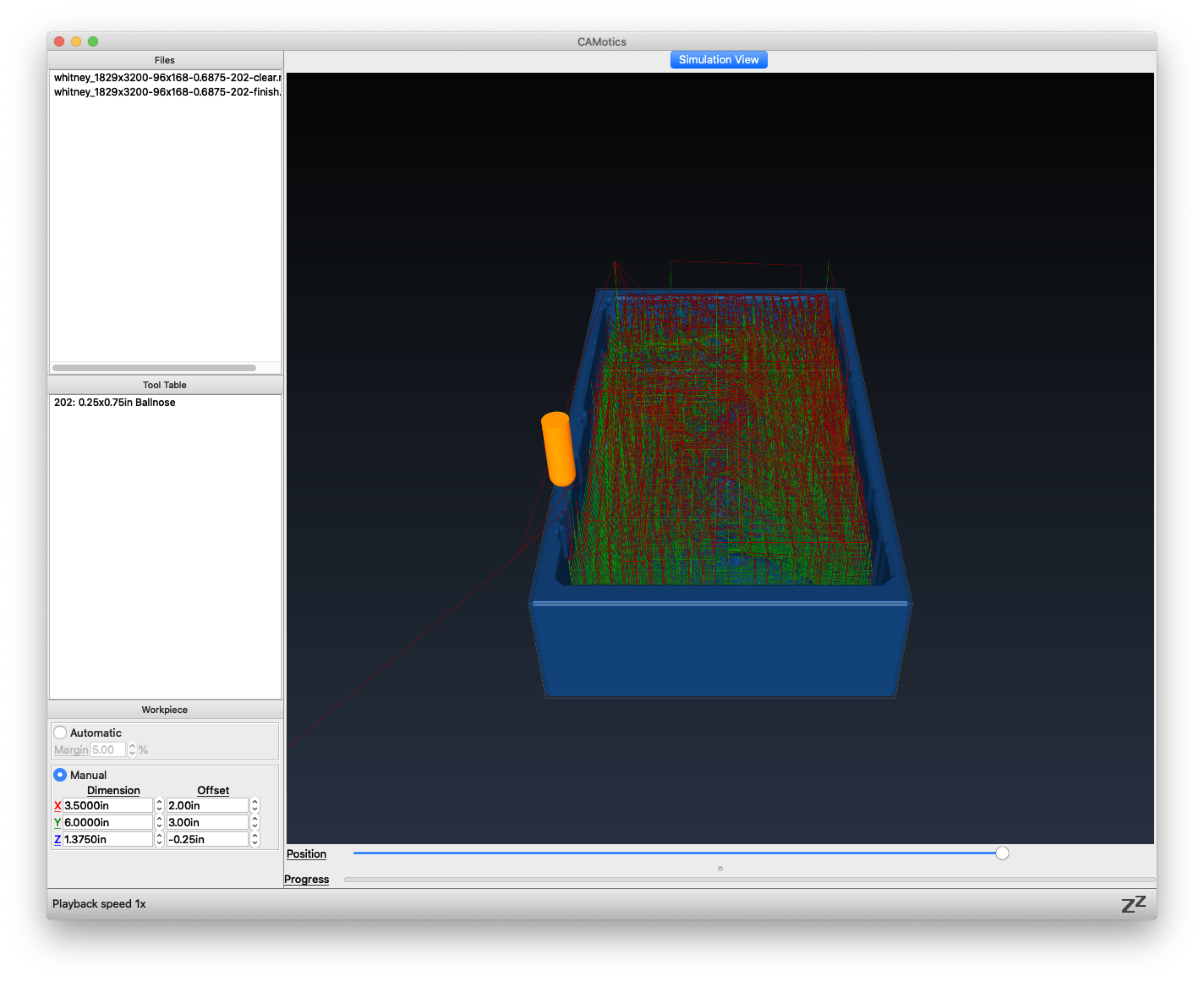
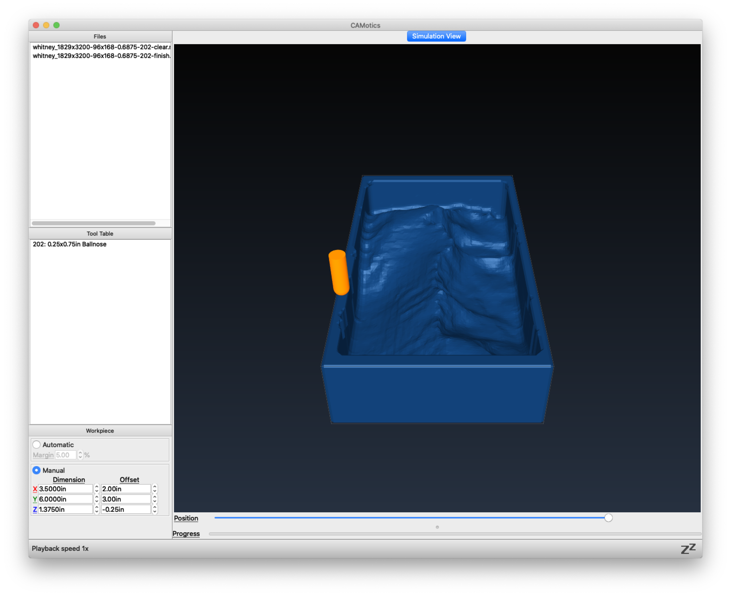
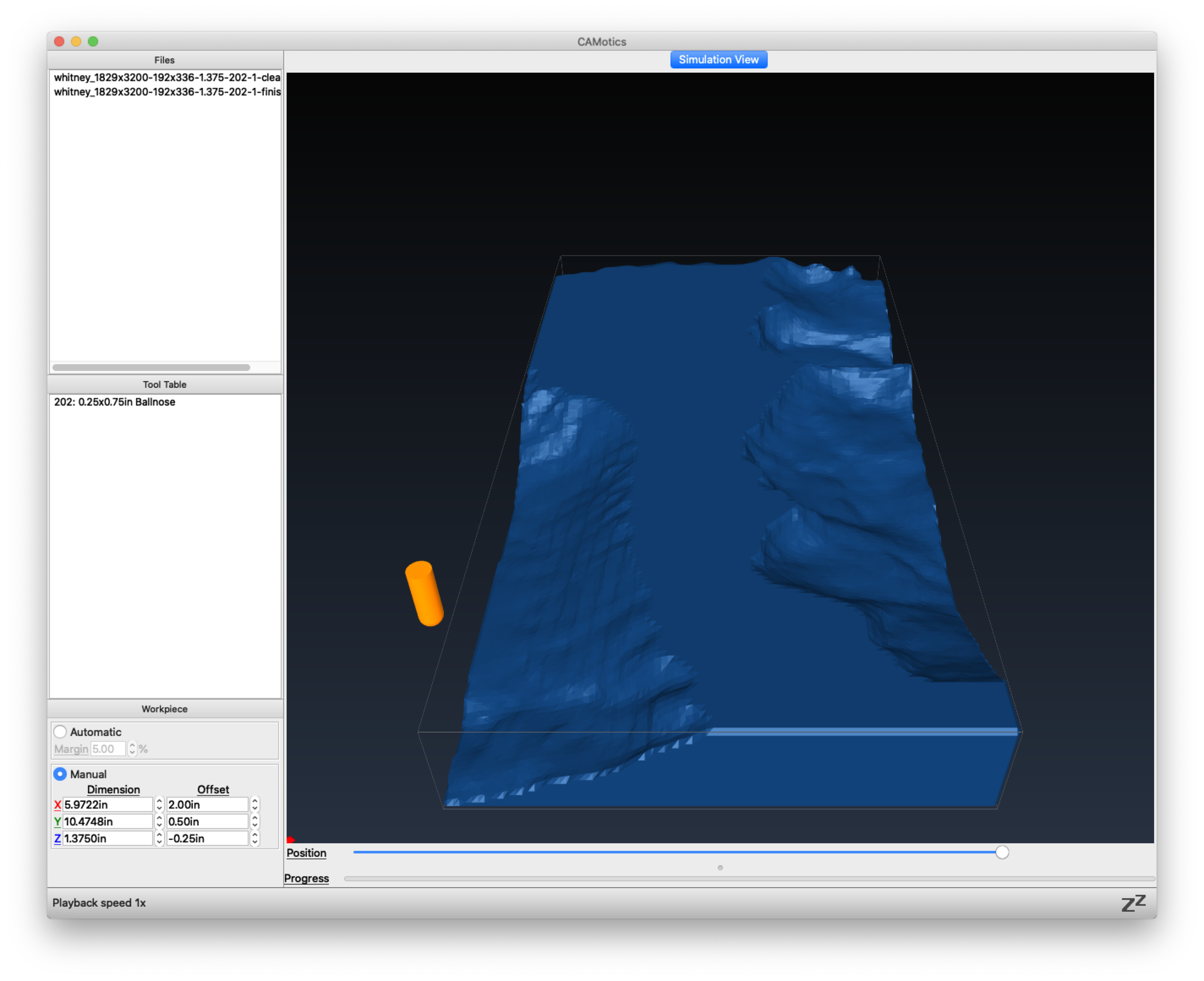
Using everything I had learned, and building on the Python CNC milling library I had been developing, I generated a new contour-following toolpath for my Mt Whitney model.
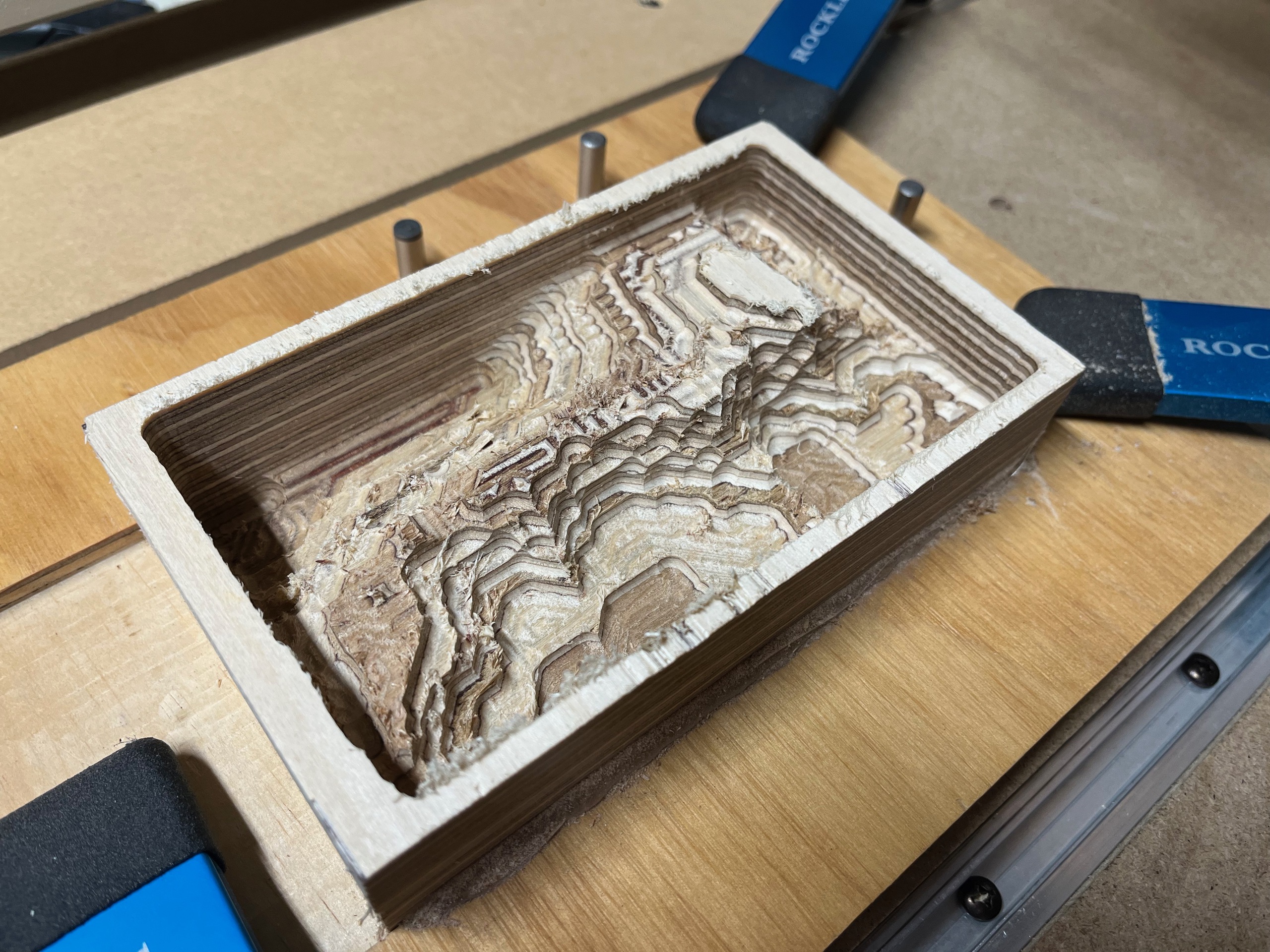
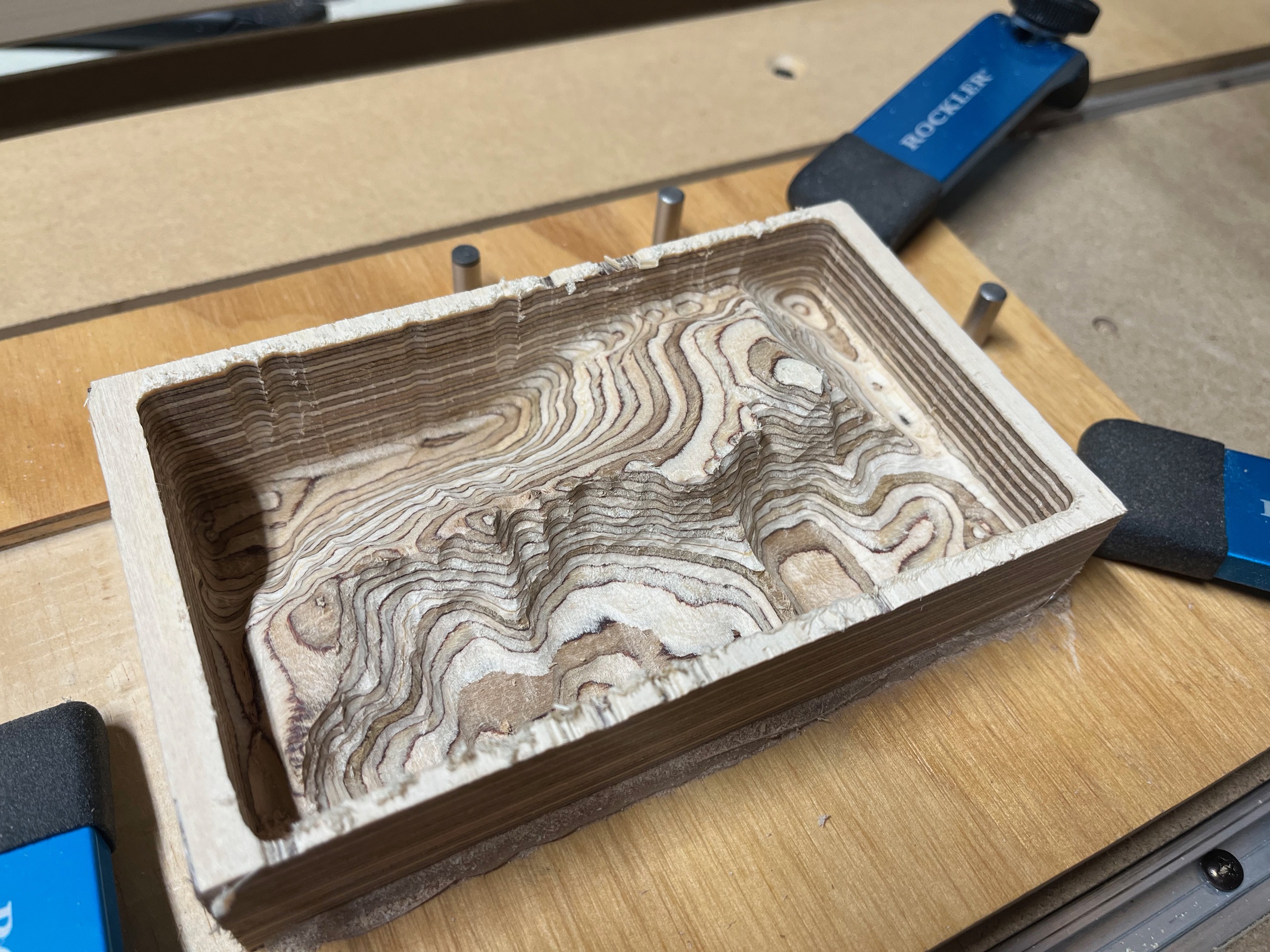
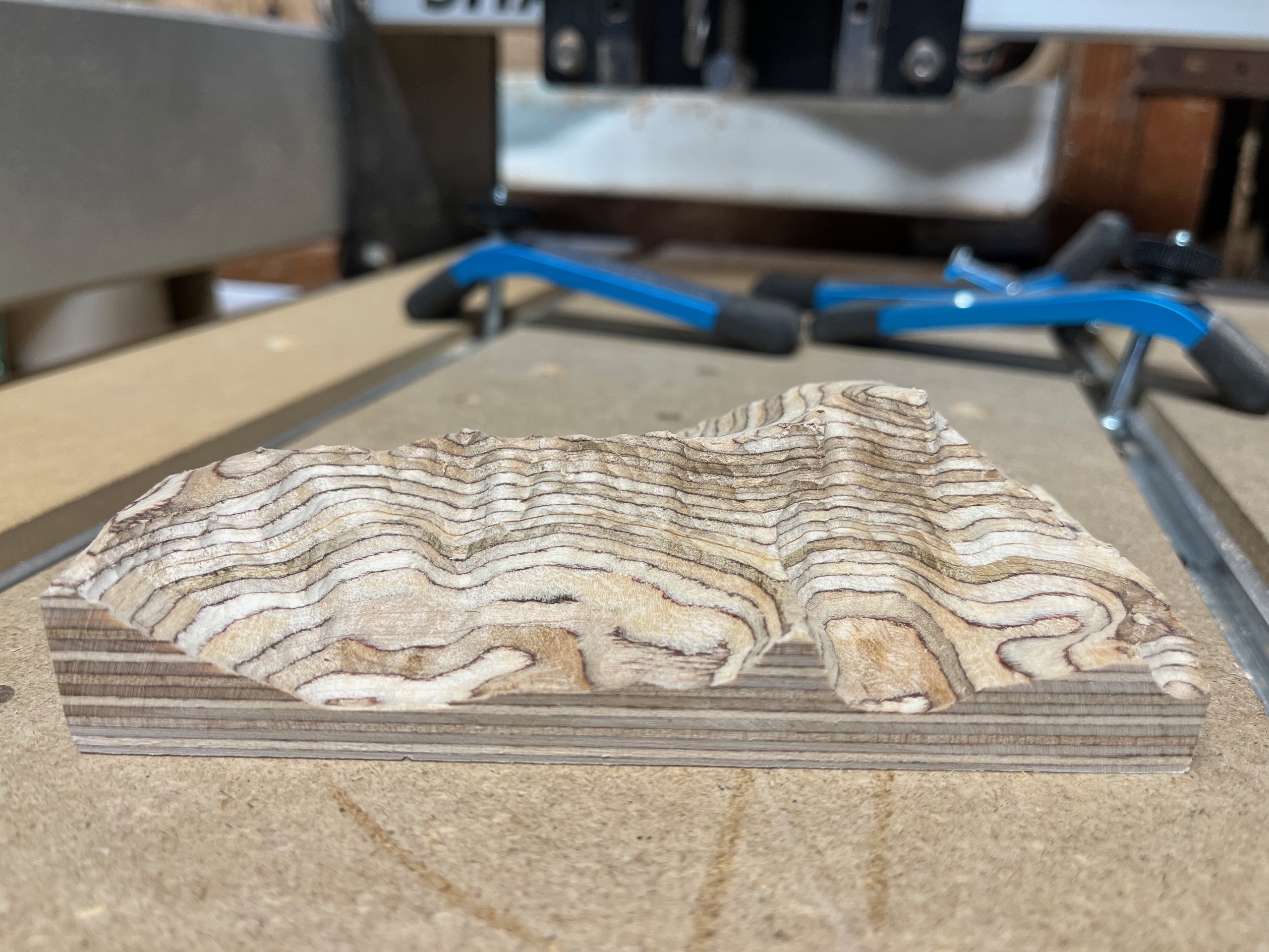
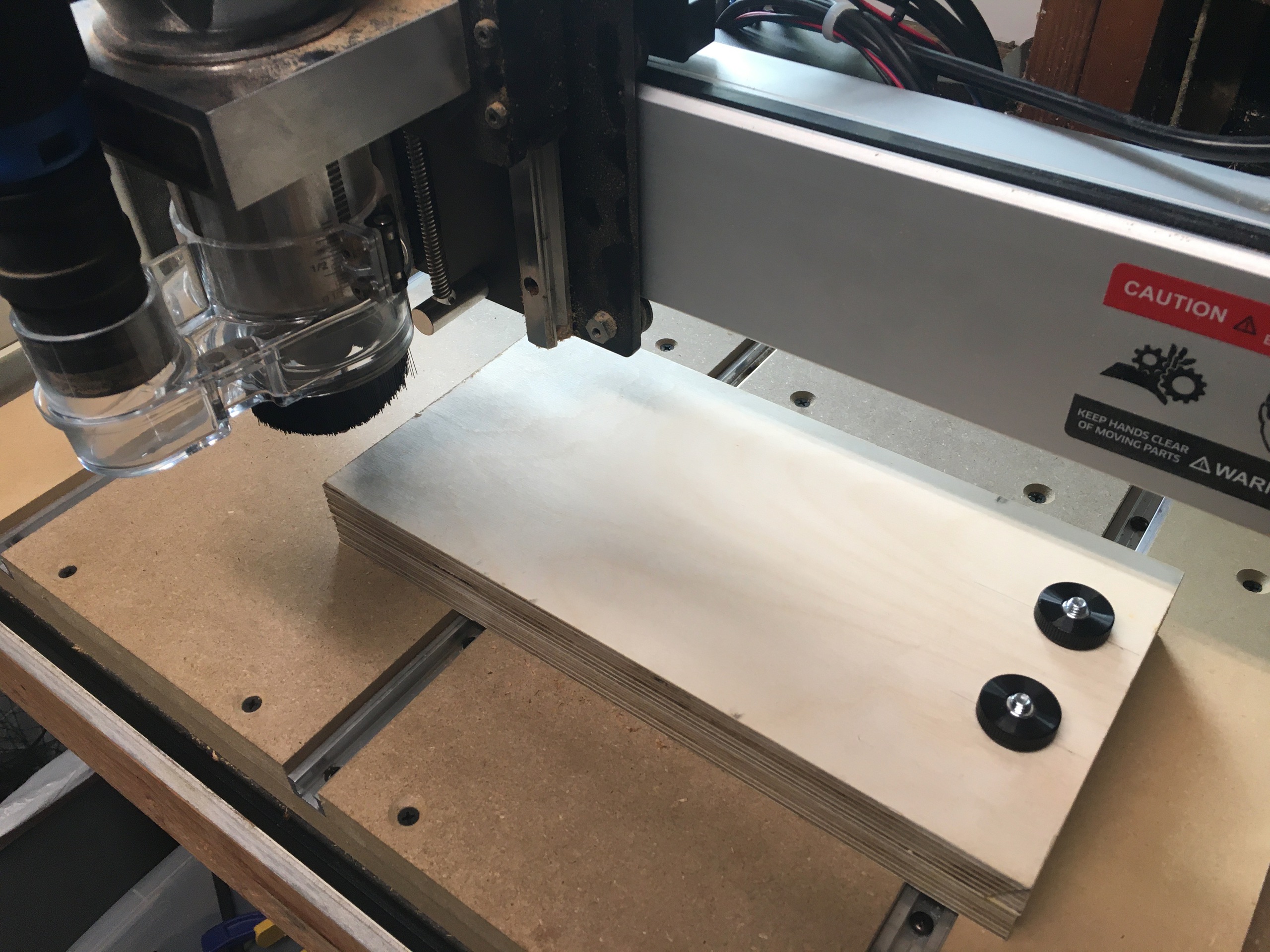
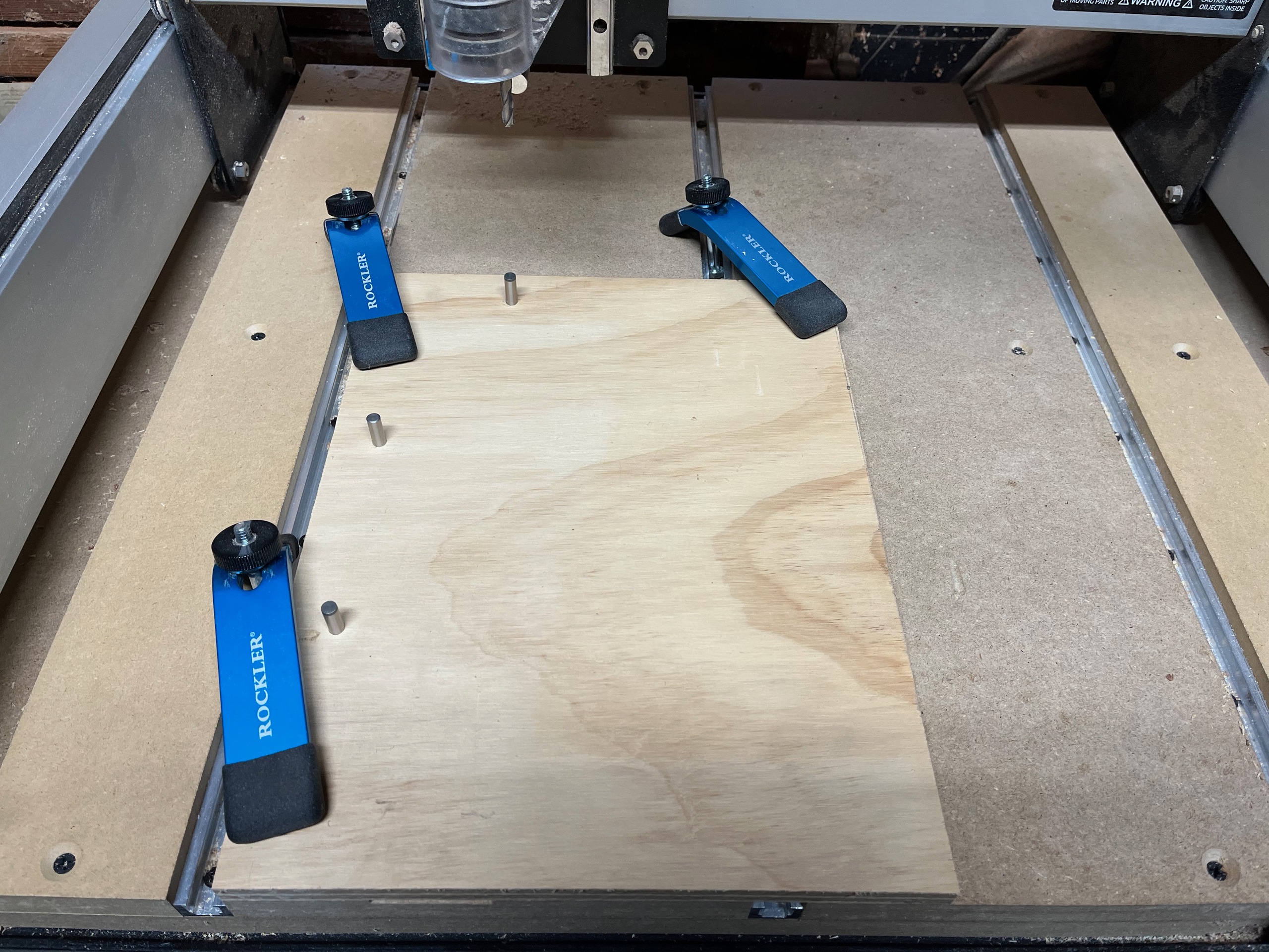
I tested the new contour toolpath by cutting another 1:24000 scale model in Birch plywood. I did a first pass to clear the bulk of the material and a second pass to finish the surface, both using a 1/4 inch bit. Total cutting time was about 2 hours and the surface finish looked great.
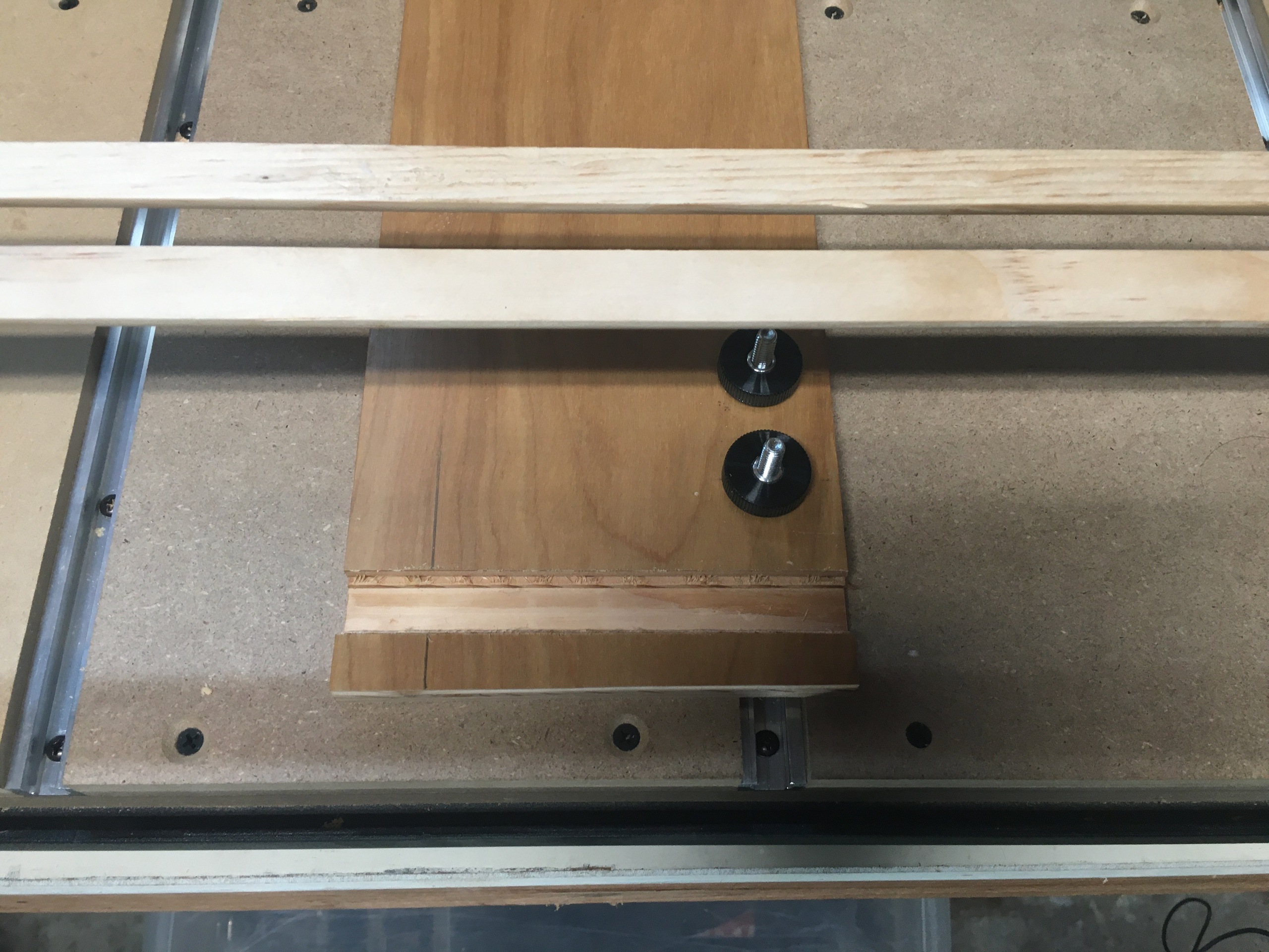
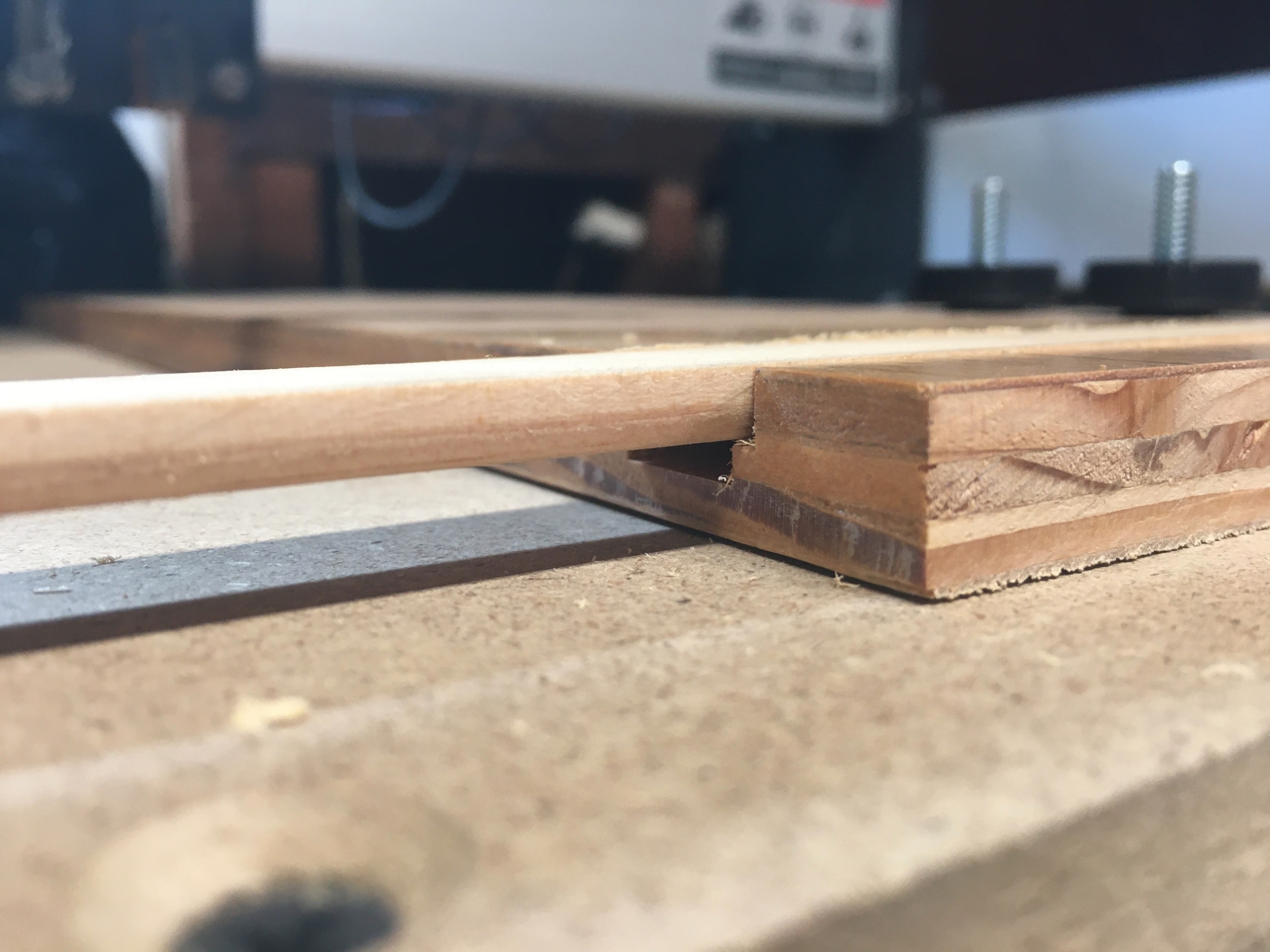
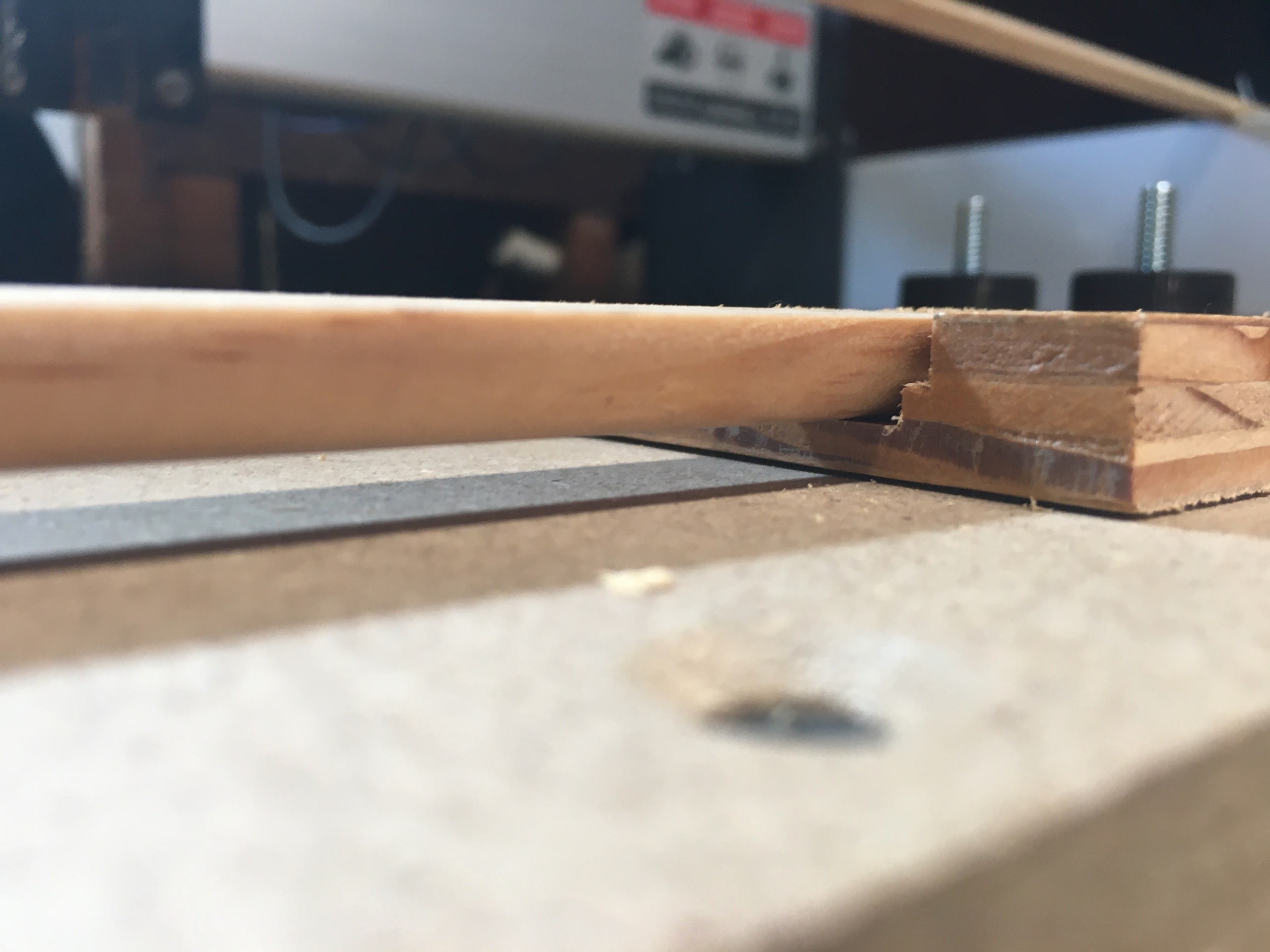
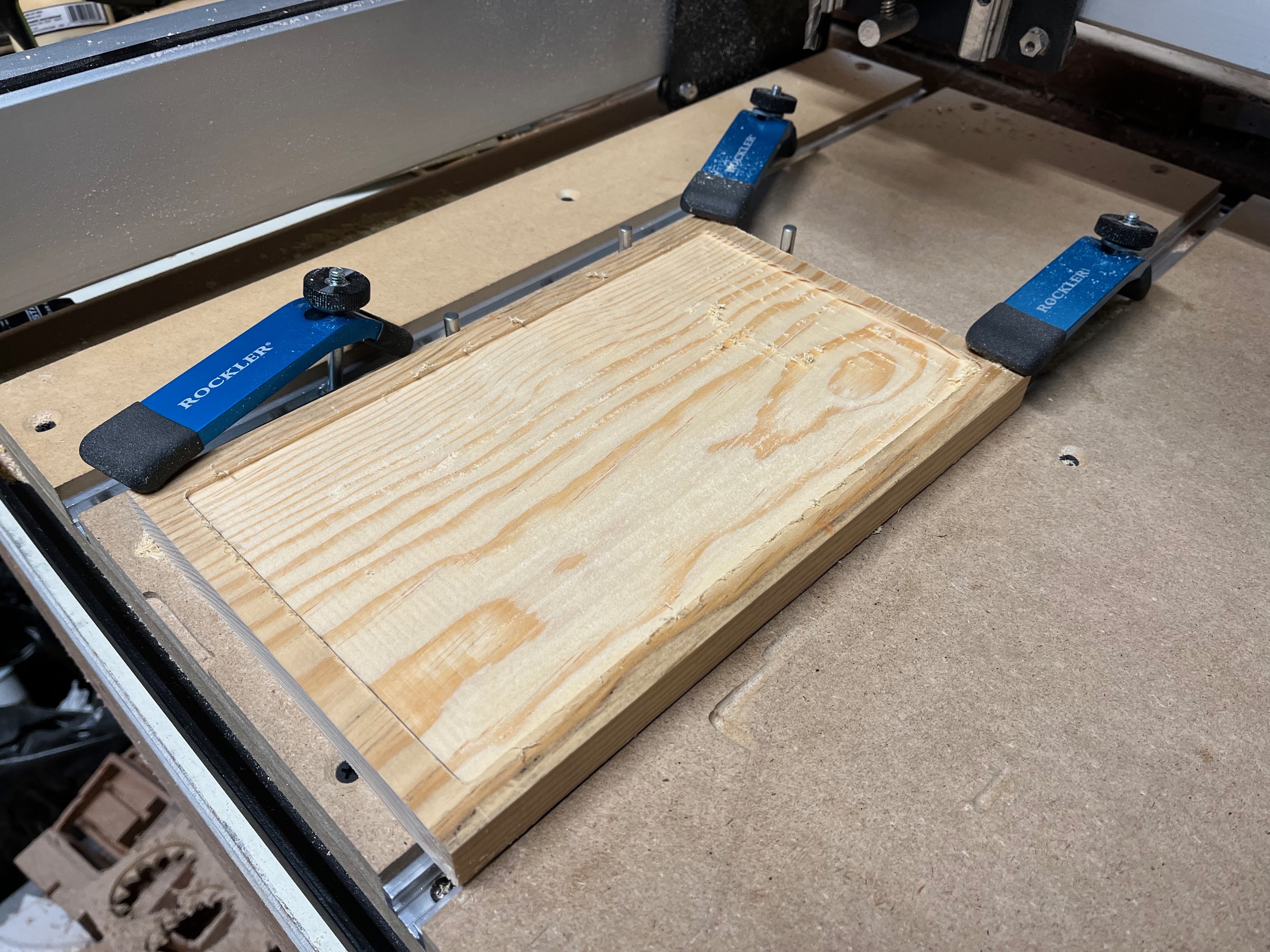
Note the improvement in my work holding technique: the stock is mounted in a jig that is pinned and clamped to the table, providing repeatable and precise placement.
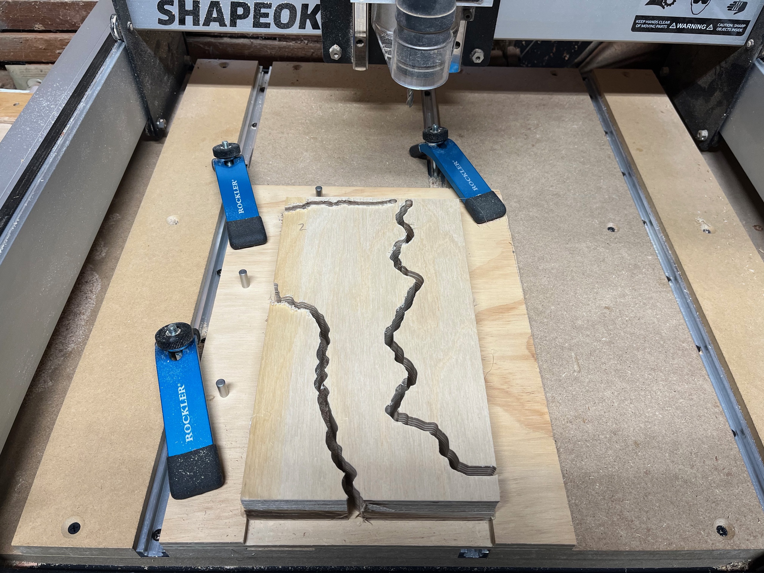
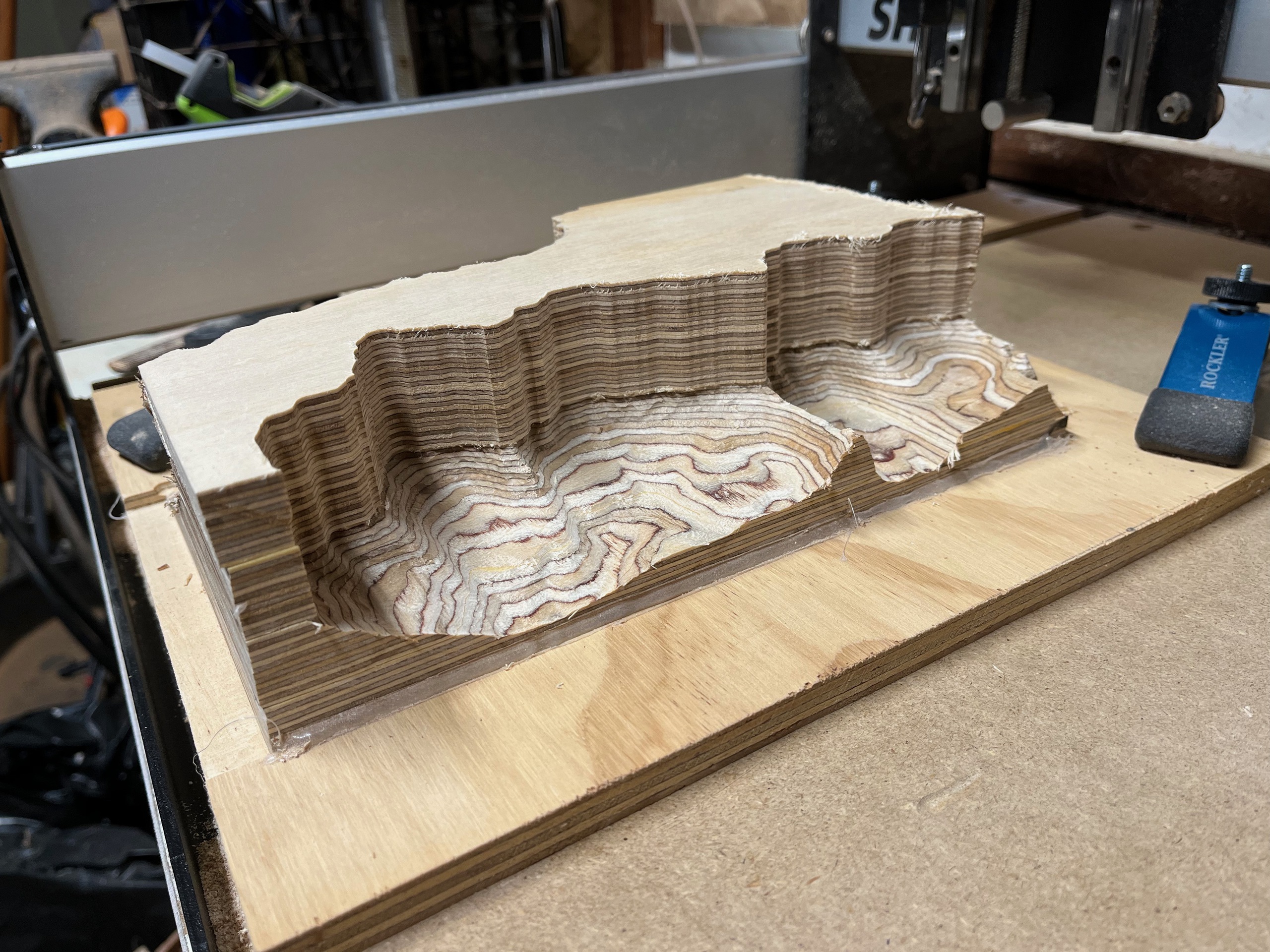
With the new toolpath working I was finally ready to cut a 6 x 10.5 x 3 inch 1:12000 scale model. This was right at the limit of my CNC machine's capacity.

Limited by the length of bit I would be able to use, I would have to cut the model in two 1.5 inch passes. My crazy idea was to cut the bottom half first and then glue on the blank for the top half and cut that in place. I thought this would have the best chance of hiding the seam between the two cuts.
I calculated the footprint of the top half of the model and generated an additional toolpath to cut the top blank to shape.
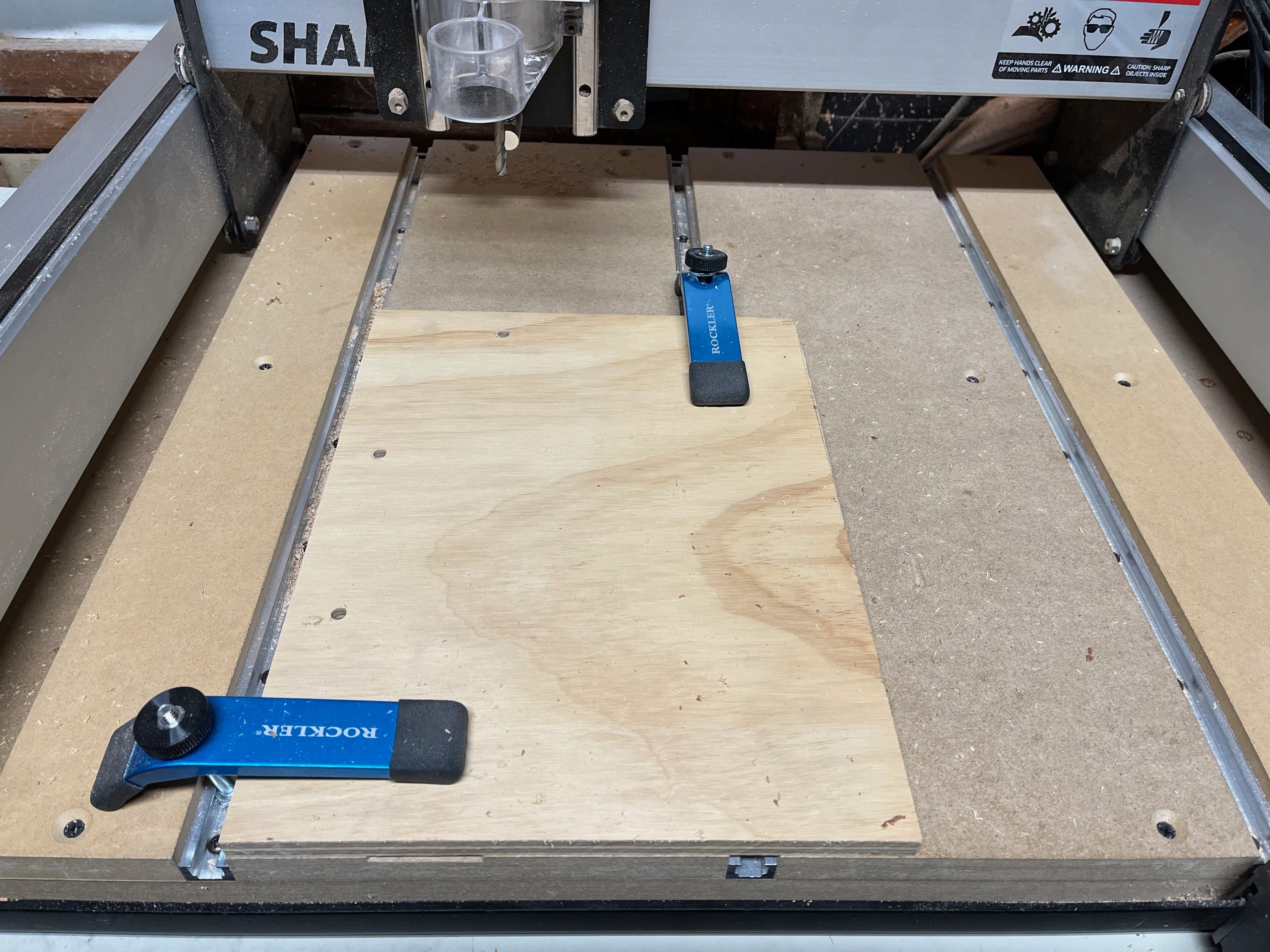
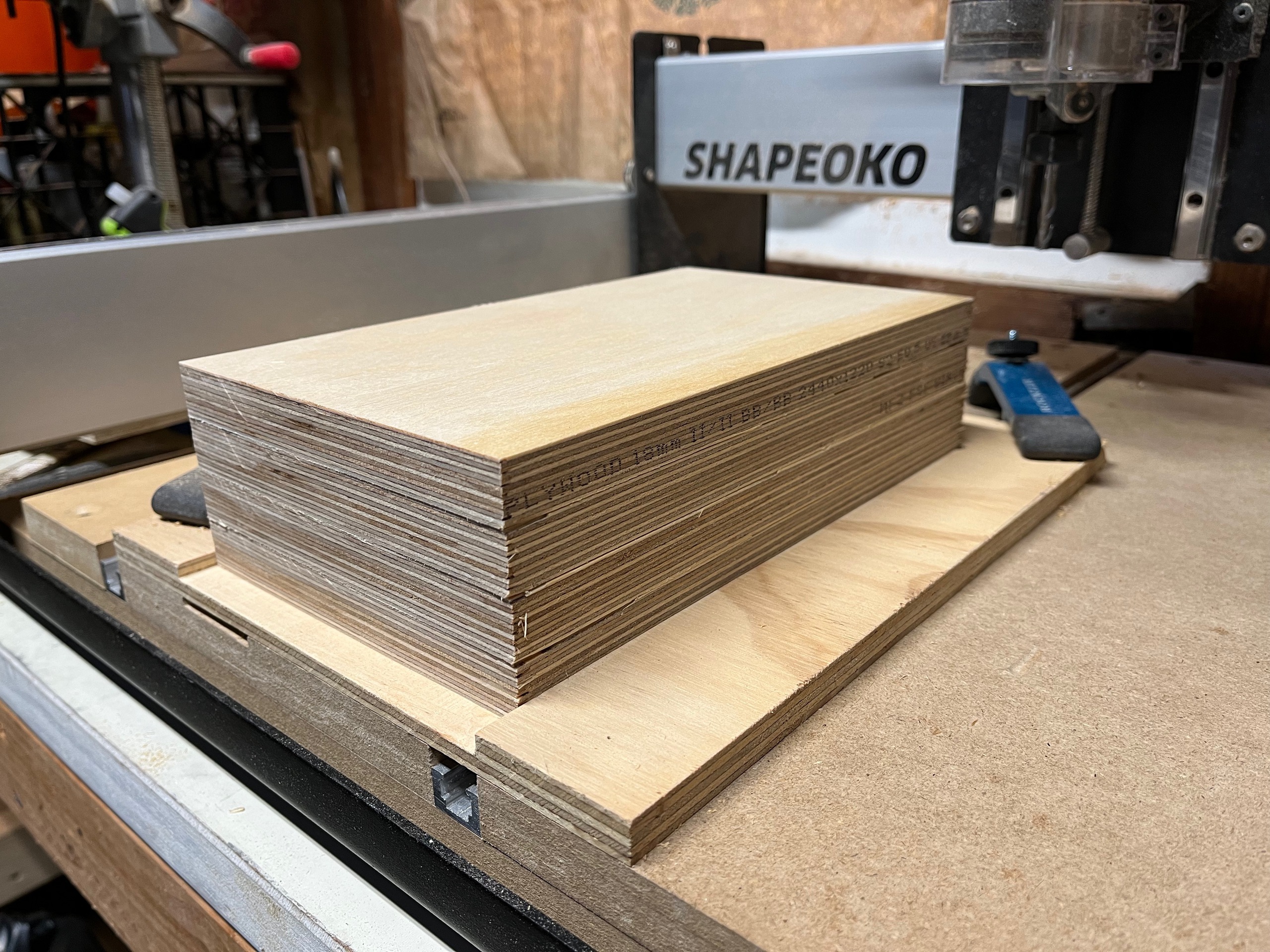
I first cut a new jig for the larger stock. The bigger model would take four 3/4 inch layers of Birch plywood.
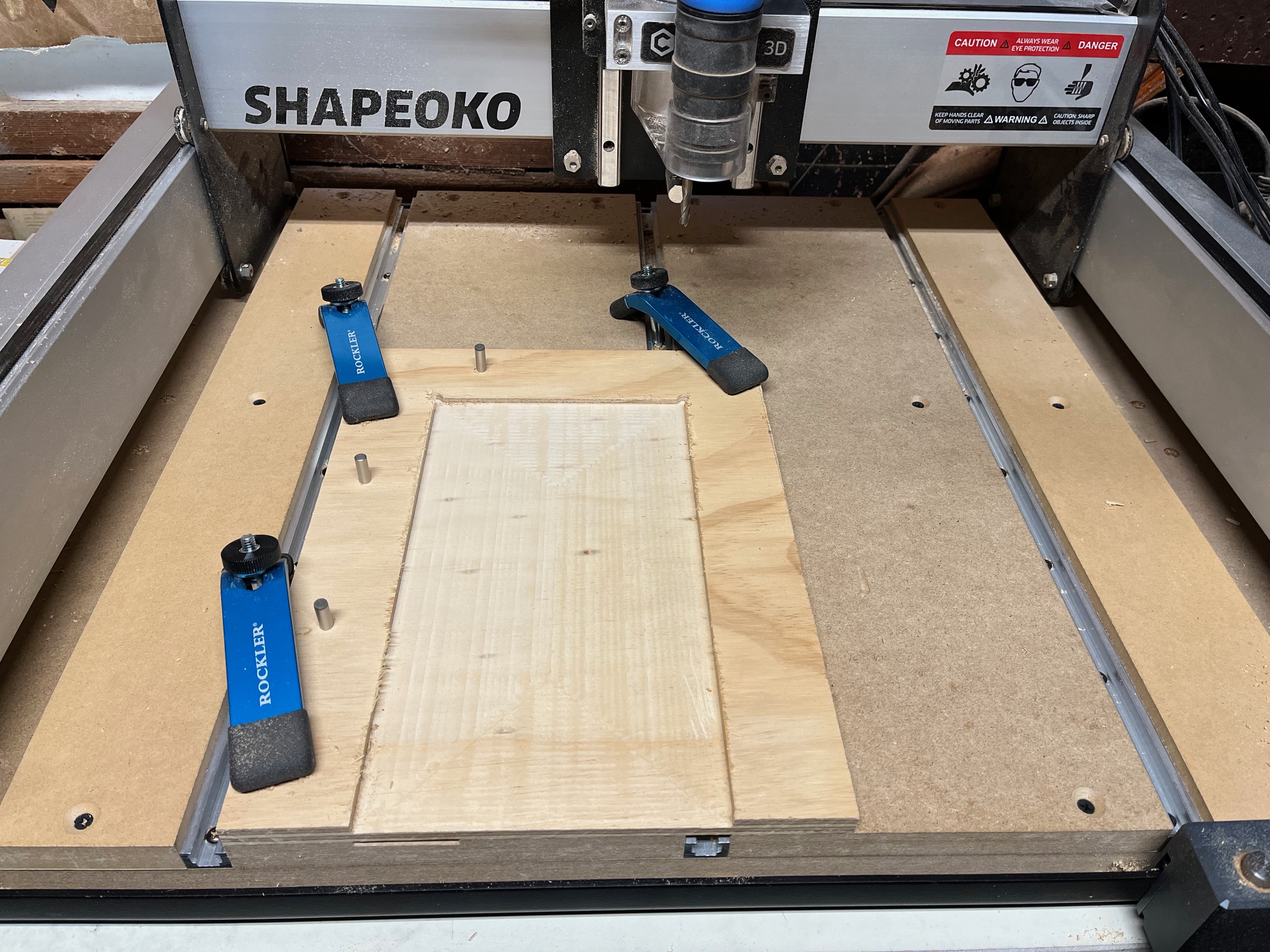
I glued up top and bottom blanks and cut the top blank to shape.
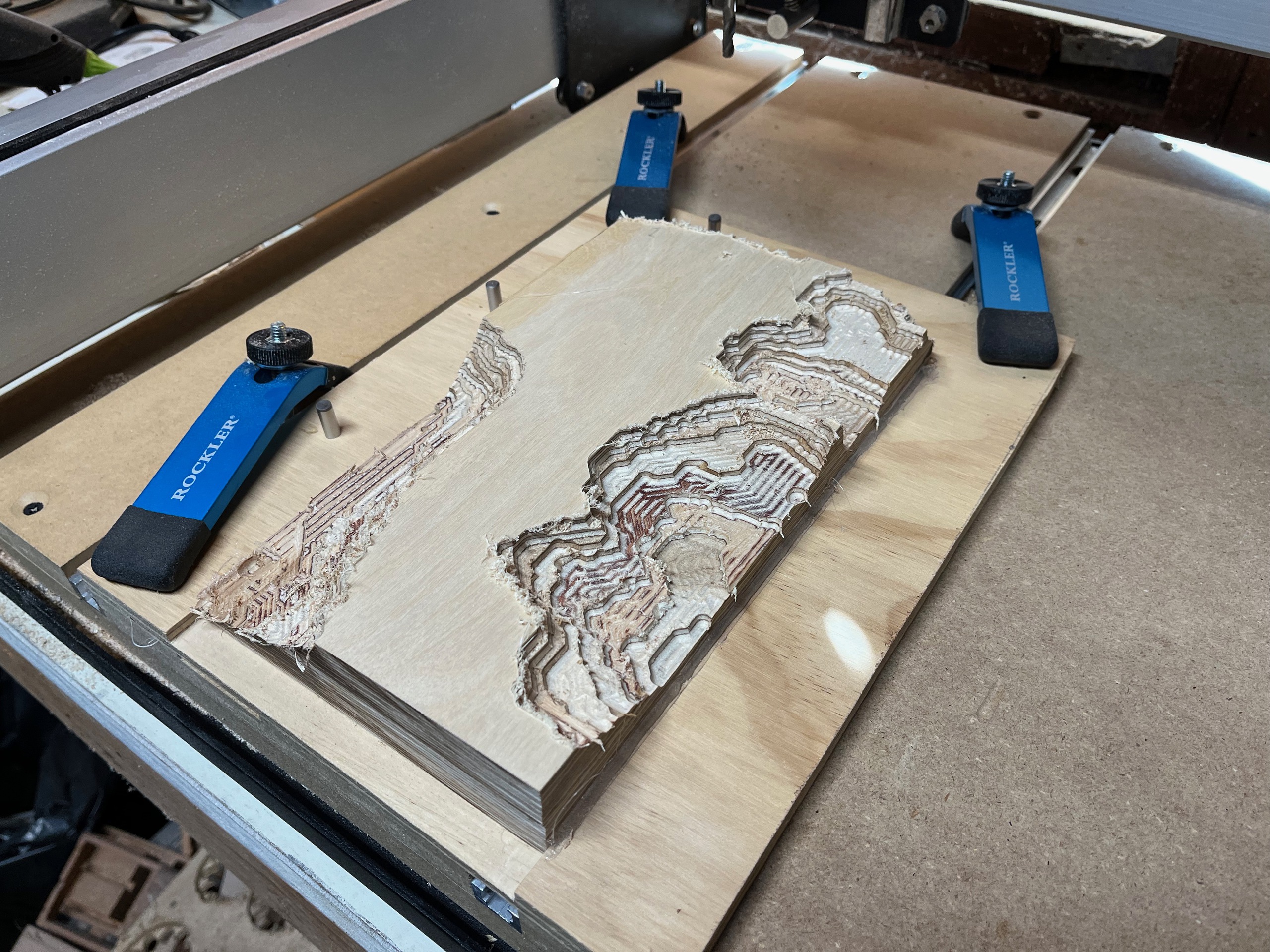
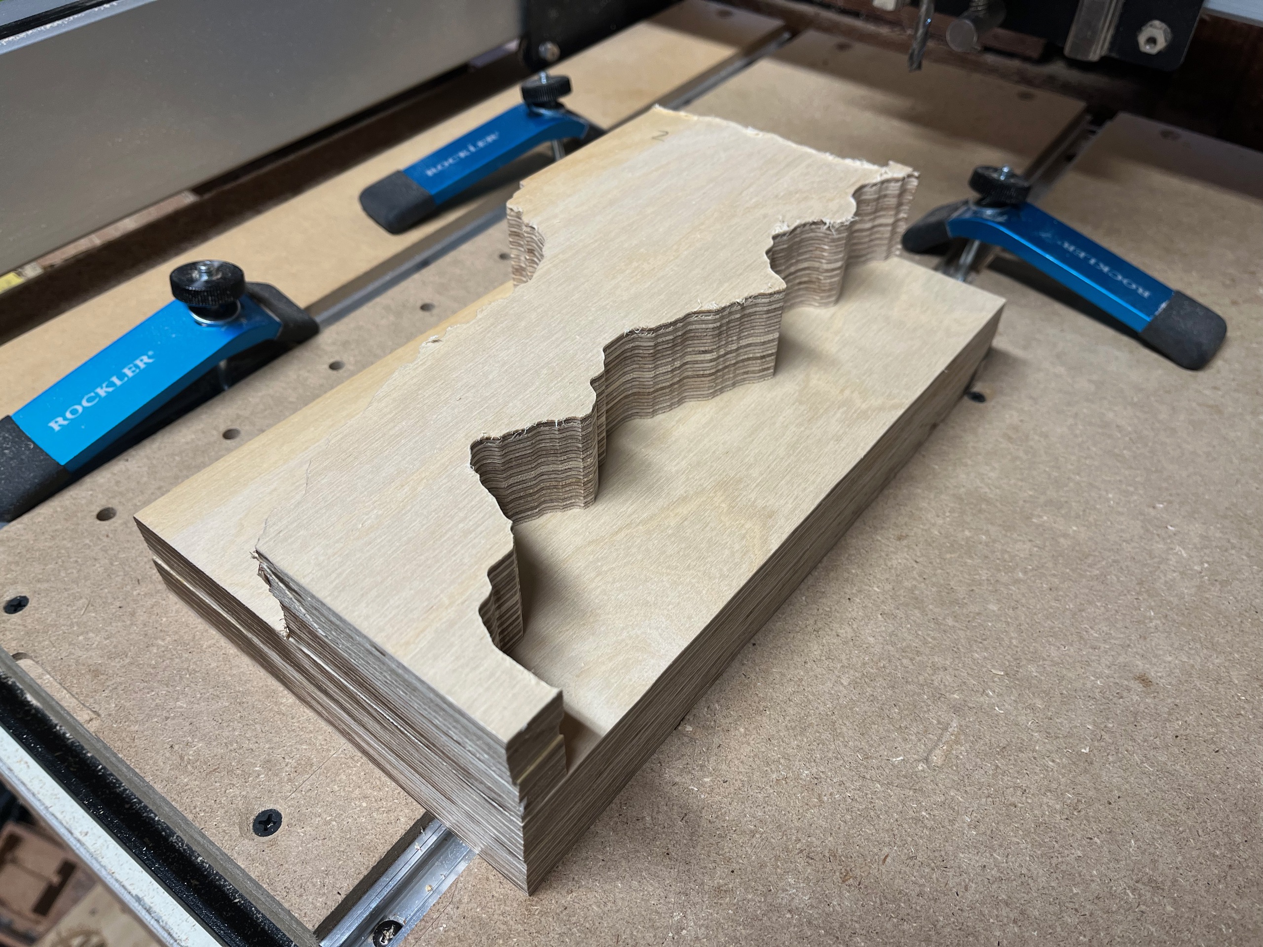
It was finally time to see if my crazy plan would work. I cut the bottom half first, doing a first pass to clear the bulk of the material and a second pass to finish surface.

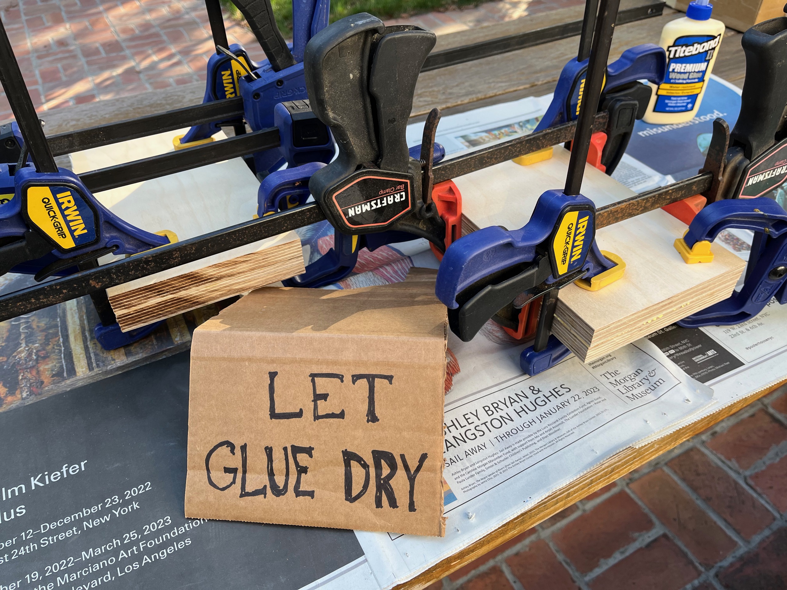
I then glued on the top blank. We're at the limit of clearance for my CNC machine!


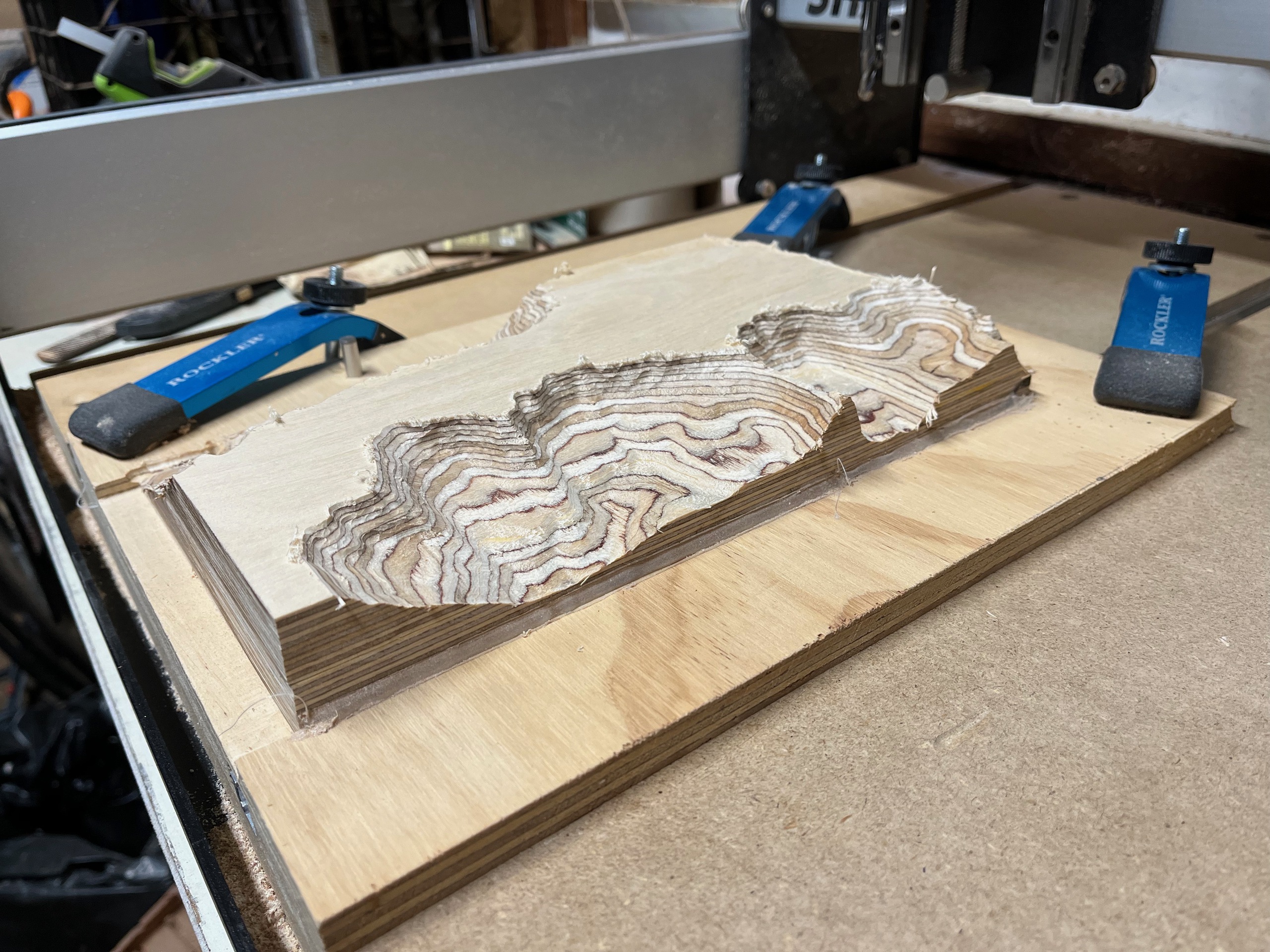
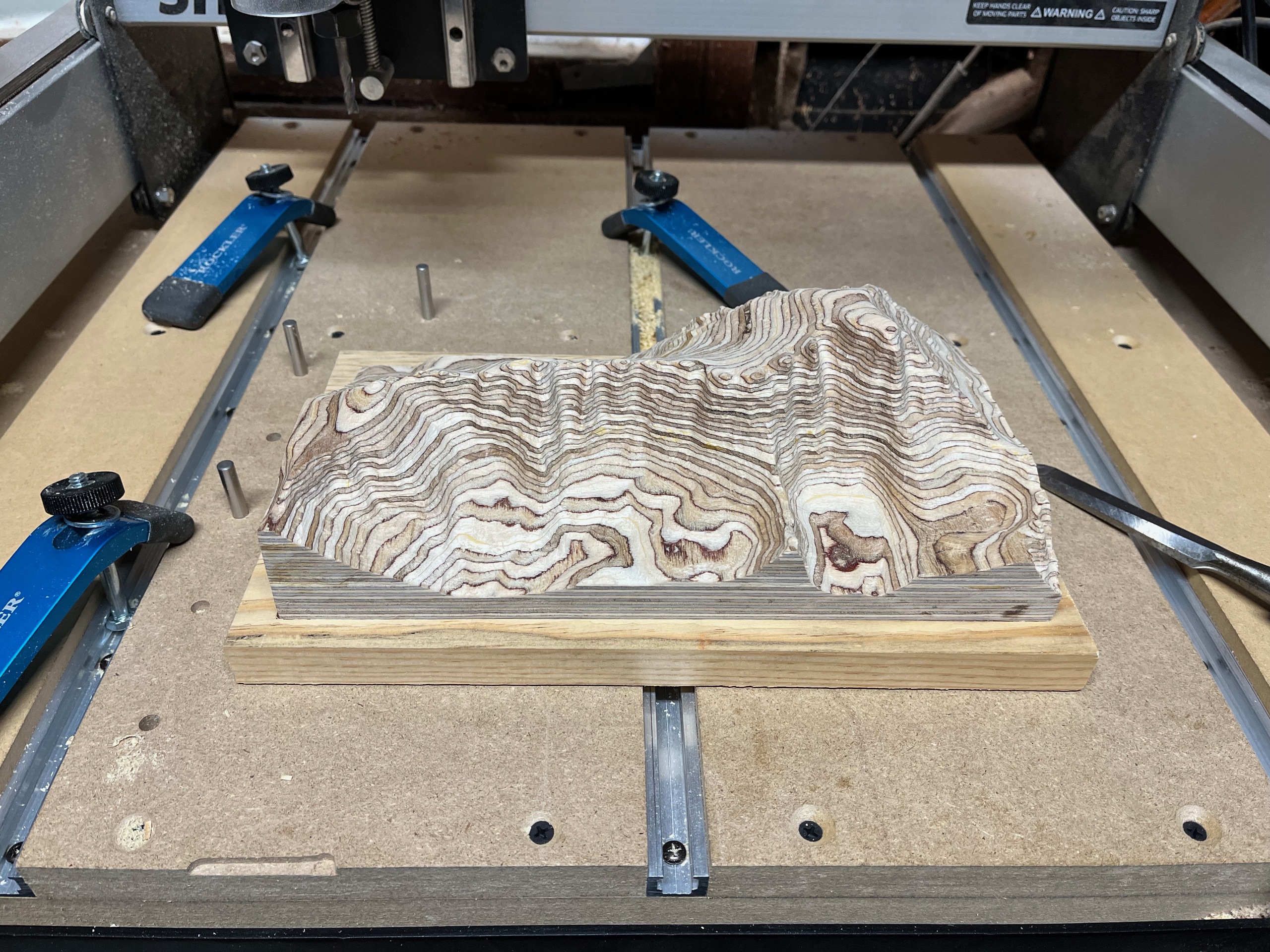
I then cut the top half in place, overlapping a tiny bit with the bottom half to clean up the glue joint. Again, doing a first pass to clear the bulk of the material and a second pass to finish the surface. Total cutting time was about 8 hours.
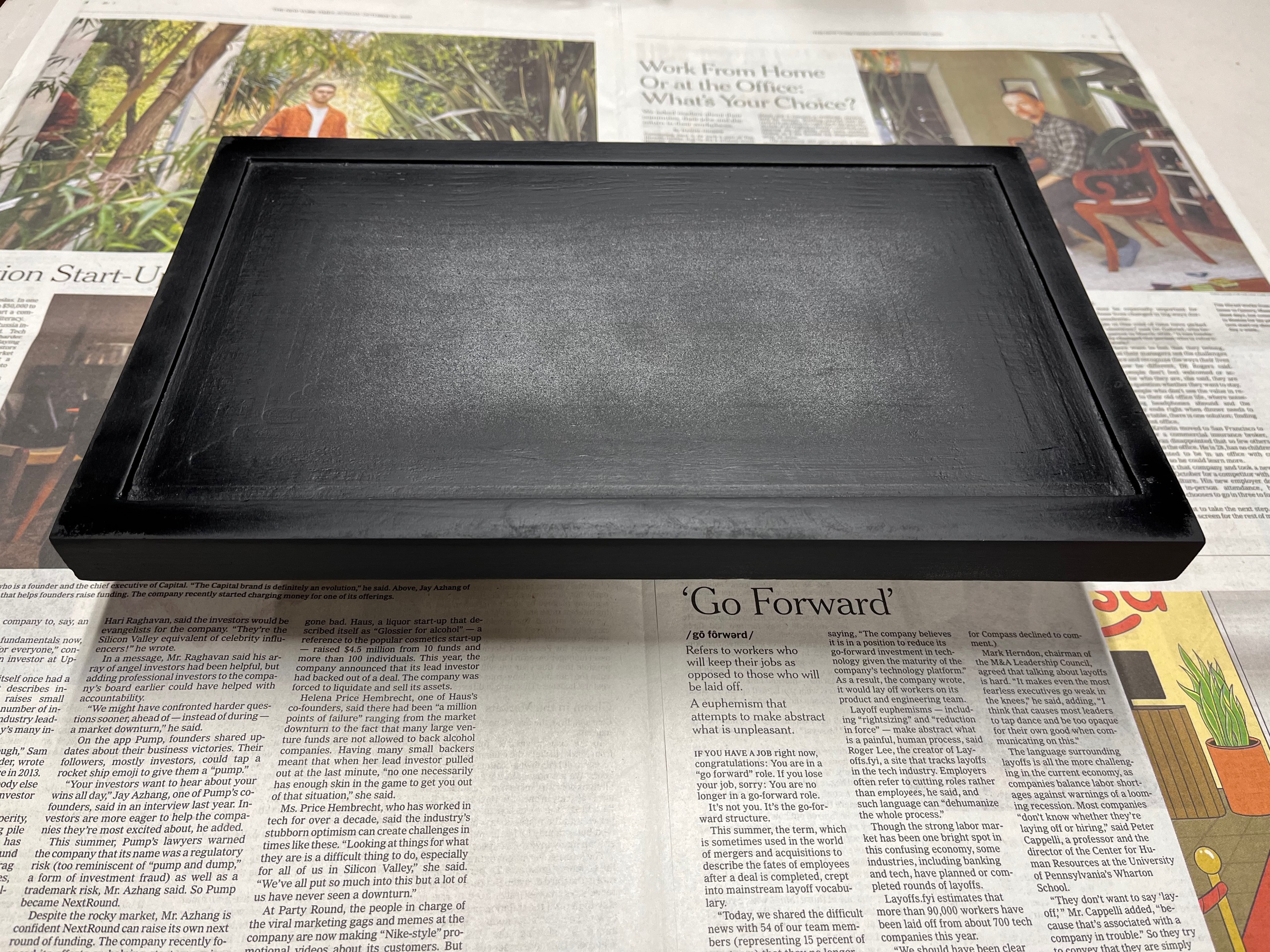
I also made a stand and painted it.
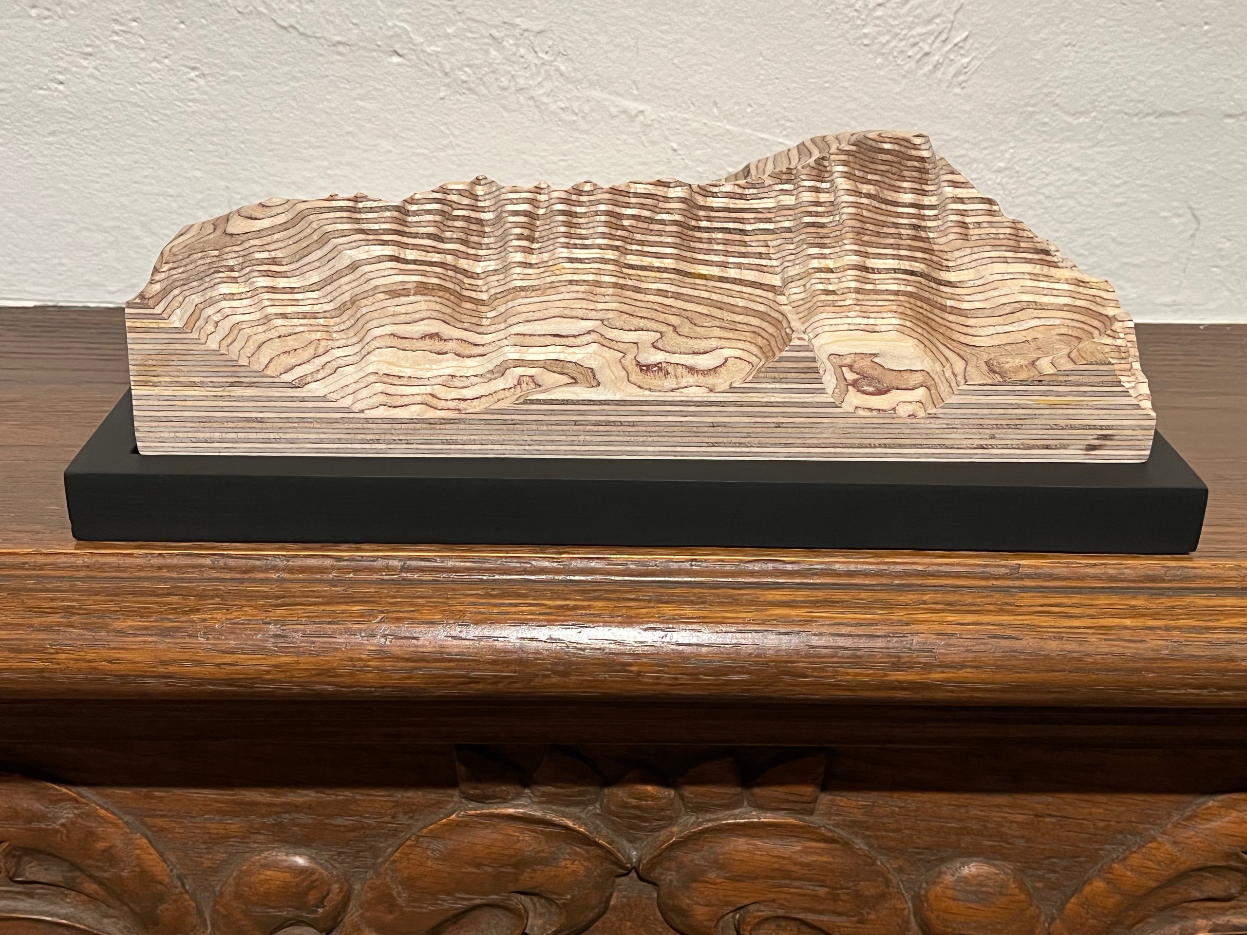
I'm super happy with how it turned out and it looks great on the mantle! The finished size is 6 x 10.5 x 3 inches and, at 1:12000 scale, each 1/16 inch ply is 62.5 feet in elevation.
Coda
Dec 2022
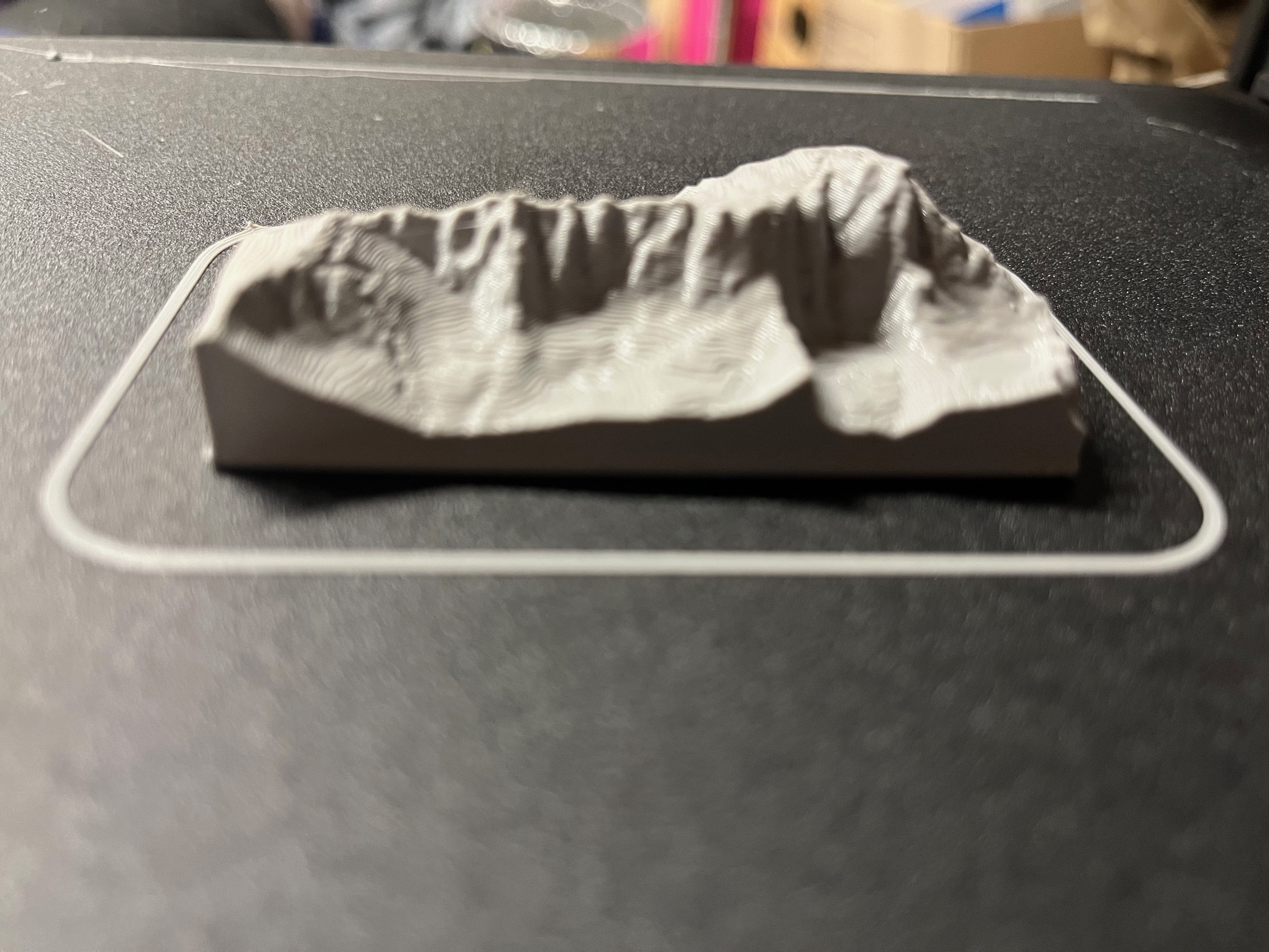

I did a 1:48000 scale 3D print. Here it is with its bigger brothers, sitting on top of a map that has been to the top of Mt Whitney.